Search the whole station Aluminum Parts twentytwentyfive

How to Avoid Machine Collision in the Machining Process?

Case Studies Resources 116

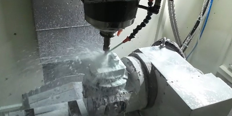
Machine collision has always been an inevitable challenge in prototype and part machining. Operator errors, such as failing to perform tool settings, can lead to crashes. It will result in broken tools, scrapped workpieces, and reordering and reprocessing materials.

In addition, without the automatic tool setter, manual tool setting when entering Z-value data error can also cause machine collision. In this article, we will share our summarized experiences to help you avoid this issue.

broken workpiece

Three Main Causes Of Machine Crashes

Before understanding how to avoid workpiece damage caused by machine collision, it is essential to understand the main reasons behind them.

Toolpath Issues By Programming Engineers

The CNC programming software MasterCam uses a method of adopting elements of surfaces and lines for machining. If the auxiliary surfaces are not fully enclosed and have missing areas, there is a risk of machine collision. However, these risks can be identified through computer-simulated machining verification, which can check for overcuts on the workpiece to avoid the risk.

CNC Operator’s Operational Issues

There are commonly three setting problems that will cause the crashing.

  • Calling the Wrong Program for Machining: CNC machine operations are controlled by program instructions. When calling a program for machining, the operator must verify that the program name, tools, and clamping lengths match the program sheet.
  • Calling the Wrong Coordinate: Sometimes, multiple workpieces are machined simultaneously on a CNC machine, there are multiple coordinates such as G54 and G56. Therefore, Calling the wrong coordinate can also lead to machine collision.
  • Missing Tool Setting or Incorrect Z-Value Data Entry: After the program starts, the tool movement needs to match the actual position of the tool tip with the Z-value data displayed on the machine screen. If there is a significant discrepancy between them, the machining process should be immediately stopped to recheck the program and tool setting data for errors.

Mechanical Failures or Tool Holder Wear

While the probability of this happening is low with regular maintenance and care of equipment and tools, it can still lead to tool drops and crashes during machining.

How To Prevent Machine Collision Using Trial Cutting Methods?

After understanding the main causes of machine collision, it should implement effective preventive measures. In this section, we will focus on how to adopt trial-cutting methods to avoid machine collision when tool setting is missed or Z-value data entry errors occur.

Trial Cutting Method for Workpieces with Frames

When a workpiece has a frame, the boundary line is typically used for trial cutting. As shown in the figure, the yellow line represents the boundary line, and only a short distance needs to be trial cut.

trial cutting method

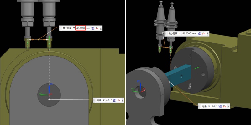
In the trial cutting process, the Z-value height should be the same as the border height. With a 200mm straight distance and a feed rate of 3000F/MIN, the trial machining time is 4 seconds, plus about 2 seconds for lowering and raising the tool, totaling around 6 seconds.

The above is a simple method that uses the same spot for trial cutting with each tool. So it is only to verify if the tool setting is too deep, avoiding overcutting or crashing.

Trial Cutting in Different Machining Areas

In most cases, except for face sweeping tools, each machining tool should perform trial machining in different areas. In the trial cutting process, the machining depth can be set to the frame plane -0.02MM. If the tool setting is correct, a slight machining mark will be visible after trial machining; if too deep, a more profound mark will appear; if too high, no mark will be seen.

Since this method relies on visual judgment, the error margin is estimated to be 0.05-0.1MM. Unlike using the same spot for trial cutting with each tool, this method checks if the tool setting is too high.

As the marked number in the above figure, the number of trial cuts can be adjusted based on the number of machining tools. However, each trial cut requires a manual judgment, taking about 2 minutes per trial, making it unsuitable for mass production.

Face Sweeping Machining for Workpieces with Frames

For parts with borders that require face machining, the first face sweeping tool does not need trial machining as its starting point is outside the workpiece.

cutting tool path

Trial Cutting for Workpieces without Frames

For workpieces without frames, such as those needing re-machining after 3-axis processing of both front and back sides. The trial cutting is done on the positioning reference or fixed block to avoid machine collision.

CNC Machining Design for Manufacturing: Expert Technical Guide

Efficient CNC design is key to balancing functionality, cost, and production efficiency. By following these guidelines, you can avoid common design challenges, improve manufacturability, and streamline the production process. From minimizing thin walls and deep cavities to setting reasonable tolerances, each recommendation in this solution helps simplify machining while ensuring quality. Let’s get to it!The depth of cavities and grooves is typically limited by the cutting tool diameter us...
CNC Machining Design for Manufacturing: Expert ...

Step Turning vs. Taper Turning: What’re the Differences?

Turning is a fundamental machining operation that has supported the manufacturing industry for centuries. It continues to evolve and is a core manufacturing technique to this day. This article will discuss two types of turning operations: step turning vs taper turning. We will explore the step process and taper turning process and explain their differences.Turning is essentially a cutting operation where a sharp cutting tool shapes a rotating workpiece by removing material from its surfa...

Step Turning vs. Taper Turning: What’re the Dif...

How to Prevent Warping and Deformation in Large and Thin-walled Shell Parts During CNC Machining?

Large, thin-walled shell parts are easy to warp and deform during machining. In this article, we will introduce a heat sink case of large and thin-walled parts to discuss the problems in the regular machining process. In addition, we also provide an optimized process and fixture solution. Let’s get to it! The case is about a shell part made of AL6061-T6 material. Here are its exact dimensions. Overall Dimension: 455*261.5*12.5mmSupport Wall Thickness: 2.5mmHeat Sink Thickness: 1.5mmHe...
How to Prevent Warping and Deformation in Large...

Causes and Solutions for Tool Marks in Machining Metal

Precision metal parts are often manufactured using various precision machining technologies, with CNC machining being a common method. Usually, precision parts typically demand high standards for both dimensions and appearance. Therefore, when using CNC machining metals such as aluminum and copper, the occurrence of tool marks and lines on the finished product’s surface is a concern. This article discusses the reasons that cause tool marks and lines during the machining of metal products....

Causes and Solutions for Tool Marks in Machinin...
Expand more!