أسباب علامات الأدوات في تصنيع المعادن بالماكينات وحلولها
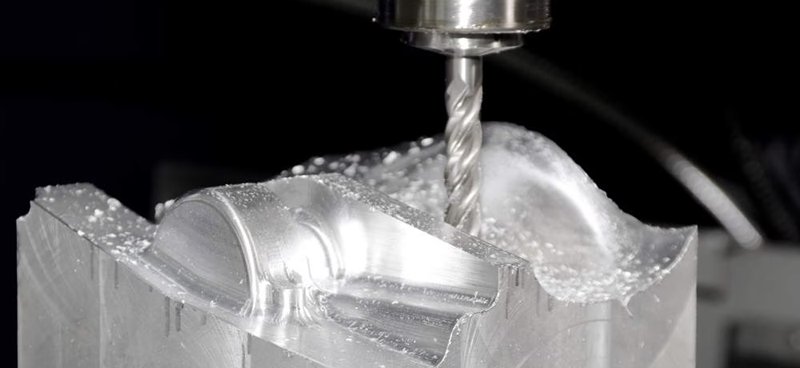
Precision metal parts are often manufactured using various precision machining technologies, with CNC machining being a common method. Usually, precision parts typically demand high standards for both dimensions and appearance.
Therefore, when using CNC machining metals such as aluminum and copper, the occurrence of tool marks and lines on the finished product’s surface is a concern. This article discusses the reasons that cause tool marks and lines during the machining of metal products. We also propose potential solutions.
Insufficient Clamping Force of Fixtures
Causes: Some cavity metal products need to use vacuum fixtures, and may struggle to generate sufficient suction due to the presence of surface irregularities, resulting in tool marks or lines.
Solution: To mitigate this, consider transitioning from simple vacuum suction to vacuum suction combined with pressure or lateral support. Alternatively, explore alternative fixture options based on specific part structures, tailoring the solution to the particular problem.
Process-related Factors
Causes: Certain product manufacturing processes may contribute to the issue. For instance, products like tablet PC rear shells undergo a sequence of machining steps involving punching side holes followed by CNC milling of the edges. This sequence can lead to noticeable tool marks when milling reaches the side-hole positions.
Solution: A common instance of this problem occurs when the aluminum alloy is chosen for electronic product shells. To resolve it, the process can be modified by replacing the side hole punching plus milling with only CNC milling. At the same time, ensuring consistent tool engagement and reducing uneven cutting when milling.
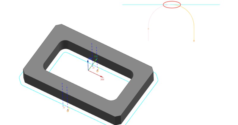
Inadequate Programming of Tool Path Engagement
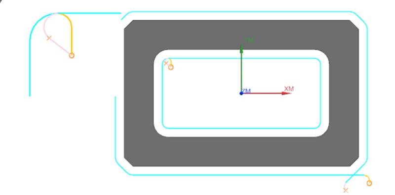
Causes: This issue commonly arises during the 2D contour machining phase of product production. Poorly designed tool path engagement in the CNC program, leaving traces at the entry and exit points of the tool.
Solution: To address the challenge of avoiding tool marks at entry and exit points, a typical approach involves introducing a slight overlap in tool engagement distance (approximately 0.2mm). This technique serves to circumvent potential inaccuracies in the machine’s lead screw precision.
While this strategy effectively prevents the formation of tool marks, it causes an element of repetitive machining when the material of the product is a soft metal. Consequently, this section may exhibit variations in texture and color compared to other areas.
Fish Scale Patterns on Flat Machined Surfaces
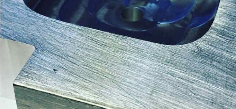
Causes: Fish scale or circular patterns appearing on the product’s flat surfaces. The cutting tools used for processing soft metals such as aluminum/copper are generally alloy material mills with 3 to 4 flutes. They have a hardness ranging from HRC55 to HRC65. These milling cutting tools are performed using the bottom edge of the tool, and the part surface may develop distinctive fish scale patterns, impacting its overall appearance.
Solution: Commonly observed in products with high flatness requirements and flat surfaces featuring recessed structures. A remedy is to switch to cutting tools made from synthetic diamond material, which helps achieve smoother surface finishes.
Aging and Wear of Equipment Components
Causes: The tools mark on the product surface is attributed to the aging and wear of the equipment’s spindle, bearings, and lead screw. Additionally, inadequate CNC system backlash parameters contribute to pronounced tool marks, particularly when machining rounded corners.
Solution: These issues stem from equipment-related factors and can be addressed by targeted maintenance and replacement.
Conclusion
Achieving an ideal surface in the CNC machining metals demands useful approaches. There are different methods to avoid tool marks and lines that involve a combination of equipment maintenance, fixture enhancements, process adjustments, and programming refinements. By understanding and rectifying these factors, manufacturers can ensure that precision components not only meet dimensional criteria but also exhibit the desired aesthetic qualities.
التوصيات
ما هو SFM؟ الدليل الكامل للقدم السطحية في الدقيقة في التصنيع الآلي
SFM، وتعني الأقدام السطحية في الدقيقة في التصنيع الآلي باستخدام الحاسب الآلي، تقيس سرعة تحرك أداة القطع عبر قطعة العمل. يتم التعبير عنها بالقدم في الدقيقة. يجمع SFM بين قطر الأداة أو قطر قطعة العمل وسرعة عمود الدوران (RPM). ينتج عن القطر الأكبر أو عدد دورات في الدقيقة أعلى في الدقيقة سرعة SFM أعلى. يستخدم صانعو الماكينات قدم السطح في الدقيقة لتحديد أفضل سرعة قطع لمادة ما. المواد المختلفة لها قيم SFM موصى بها للأداء الأمثل. على سبيل المثال، يحتوي الفولاذ المقاوم للصدأ الملدن 303 على...

Press Fit Tolerance: Defination, Practices, And Calculation
The manufacturing industry is highly precision-centric, where even the slightest of margins can create huge differences in product quality, cost, and utility. This article discusses the topic of press fitting, where a few micrometers of deviation dictates the criterion for part failure. So, what is press fit and, the factors influencing press fit tolerancing, and present an example of a press fit calculator. We will also share some key tips to keep in mind while designing components for p...

كيف يمكن منع الالتواء والتشوه في الأجزاء الهيكلية الكبيرة ورقيقة الجدران أثناء التصنيع باستخدام الحاسب الآلي؟
من السهل التواء وتشوه الأجزاء الكبيرة ذات الجدران الرقيقة أثناء التشغيل الآلي. في هذه المقالة، سوف نقدم حالة المشتت الحراري للأجزاء الكبيرة ورقيقة الجدران لمناقشة المشاكل في عملية التصنيع الآلي العادية. بالإضافة إلى ذلك، نقدم أيضًا حلًا محسنًا للعملية والتركيبات. لنبدأ العمل! تتعلق الحالة بجزء غلاف مصنوع من مادة AL6061-T6. فيما يلي أبعادها الدقيقة. البعد الكلي: 455*261.5*12.5 مم سماكة الجدار الداعم: 2.5 مم سماكة حوض الحرارة: 1.5 مم...

الخراطة المتدرجة مقابل الخراطة المستدقة: ما هي الاختلافات؟
الخراطة هي عملية تصنيع أساسية دعمت الصناعة التحويلية لعدة قرون. وتستمر في التطور وهي تقنية تصنيع أساسية حتى يومنا هذا. سوف تناقش هذه المقالة نوعين من عمليات الخراطة: الخراطة التدريجية مقابل الخراطة المستدقة. سوف نستكشف عملية الخراطة التدريجية وعملية الخراطة المستدقة ونوضح الاختلافات بينهما. الخراطة هي في الأساس عملية قطع حيث تقوم أداة القطع الحادة بتشكيل قطعة عمل دوارة عن طريق إزالة المواد من سطح الشغل.

