كيف يمكن تحديد مركز دوران الدوارة عند تشغيل ماكينة بنظام التحكم الرقمي ذات 4 محاور؟
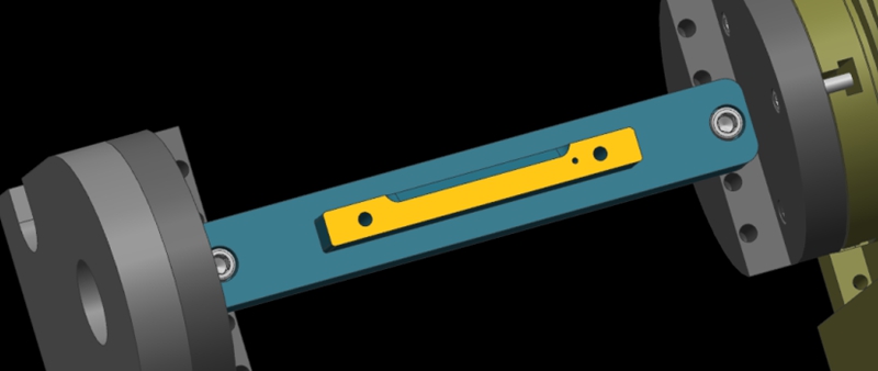
Here, we show a 4-axis rotary table that rotates around the X-axis of a machine tool, where the axis of rotation is called the A-axis. In a word, all we need to do is to determine the Y/Z coordinates of the center of rotation on the 4-axis machine.
In addition, the X coordinate values are determined by the placement of the product, so we won’t go into detail here. The following are the specific steps to determine the center of rotation.
Step 1: Calibrate the Fixture Reference Plane
Firstly, use the calibration table to calibrate the fixture datum plane (the yellow surface). Then, set the calibrated datum plane to the 0 degree position of the A-axis.
Step 2: Set the Fixture Datum Plane
After setting the datum plane, we need to rotate the A-axis 90 degrees positive. Then, use a centering bar to measure the machine position where the datum plane is located. In the relative coordinate setting, set the Y coordinate to “0”.
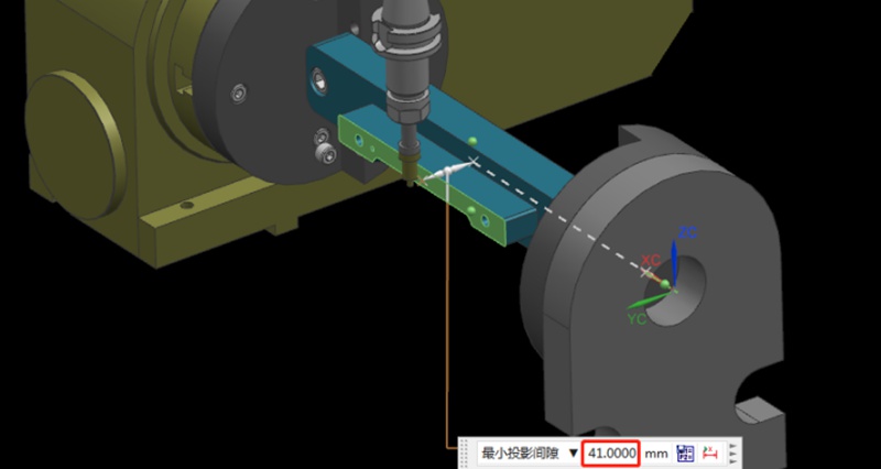
Step 3: Measure the Value of the Datum Plane
Next, rotate the A-axis 180 degrees in the negative direction. Same as the last step, we need to measure the machine position on the other side of the datum using the centering bar. Then, check the current relative Y value of the machine. For example, if we assume the Y value is “92mm”, the centering diameter is 10mm centering diameter, and the fixture datum to the rotary table is 41mm.
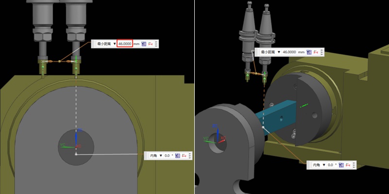
Step 4: Determine the Position of the Rotation Center in the Y-axis
Referring to the values in the previous step, we can calculate that 92/2 = 46mm, so half of the Y value of 46mm. Then, we move the centering bar 46mm negatively towards the Y-axis.
As shown by the picture, the centering bar is now just aligned with the rotational axis of the rotary table. At the time, the position of the alignment point is the zero point of the Y value of the machine. In this way, we have completed half of the operation work.

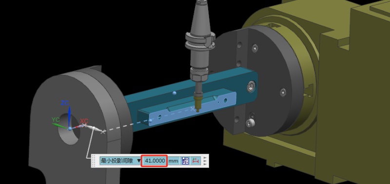
Step 5: Find the Position of the Rotation Center in the Z-axis
Finding the Z value is relatively simple. After the rotary table returns to the A0 position, the zero point of the Z-axis of the rotary axis can be determined by moving down 41mm with the datum surface as the calculation base. This value is calculated using the formula “(92-10)/2”, where 92 is the Y-value found earlier and 10 is the diameter of the centering bar. By applying this formula, the Z value is determined.
Finally, the intersection of the Z and Y axis is the rotation center around the X axis. With these steps, we can determine the rotation center of the 4-axis rotary table.
التوصيات
أسباب علامات الأدوات في تصنيع المعادن آليًا وحلولها
Precision metal parts are often manufactured using various precision machining technologies, with CNC machining being a common method. Usually, precision parts typically demand high standards for both dimensions and appearance. Therefore, when using CNC machining metals such as aluminum and copper, the occurrence of tool marks and lines on the finished product’s surface is a concern. This article discusses the reasons that cause tool marks and lines during the machining of metal products....

Types Of Milling Explained: Know All Milling Operations
Milling is inarguably the backbone of the manufacturing industry, playing a direct role in high-quality production in industries including aerospace, automotive, medical, and defense. Milling operations are highly versatile and capable of handling complex geometries with precision and speed. In this article, we will discuss the fundamentals of CNC milling and explain various milling operations, helping to choose the right milling type for your applications.Milling is a machining process t...

Machining Allowance Explained: Its Calculation And Matters
Machining allowance is a fundamental concept in manufacturing. It is a common engineering practice in CNC precision machining, ensuring dimensional accuracy, surface quality, and the production of reliable and functional components for a range of industries, including aerospace, defense, and medical. This article attempts to answer the question: what is machining allowance? We will take a deep dive into the concept of machining allowance and discuss why machinists leave machining allowanc...

تصميم الماكينات بنظام التحكم الرقمي للتصنيع باستخدام الحاسوب: الدليل التقني للخبراء
Efficient CNC design is key to balancing functionality, cost, and production efficiency. By following these guidelines, you can avoid common design challenges, improve manufacturability, and streamline the production process. From minimizing thin walls and deep cavities to setting reasonable tolerances, each recommendation in this solution helps simplify machining while ensuring quality. Let’s get to it!The depth of cavities and grooves is typically limited by the cutting tool diameter us...

