¿Cómo determinar el centro de rotación de rotación al operar una máquina CNC de 4 ejes?
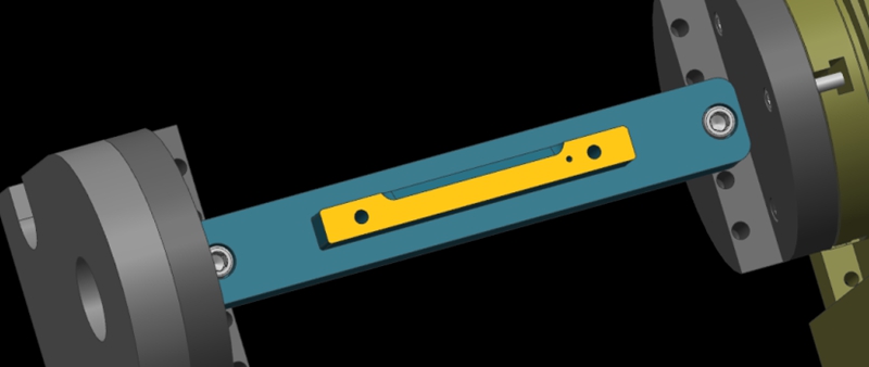
Here, we show a 4-axis rotary table that rotates around the X-axis of a machine tool, where the axis of rotation is called the A-axis. In a word, all we need to do is to determine the Y/Z coordinates of the center of rotation on the 4-axis machine.
In addition, the X coordinate values are determined by the placement of the product, so we won’t go into detail here. The following are the specific steps to determine the center of rotation.
Step 1: Calibrate the Fixture Reference Plane
Firstly, use the calibration table to calibrate the fixture datum plane (the yellow surface). Then, set the calibrated datum plane to the 0 degree position of the A-axis.
Step 2: Set the Fixture Datum Plane
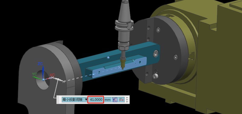
After setting the datum plane, we need to rotate the A-axis 90 degrees positive. Then, use a centering bar to measure the machine position where the datum plane is located. In the relative coordinate setting, set the Y coordinate to “0”.
Step 3: Measure the Value of the Datum Plane
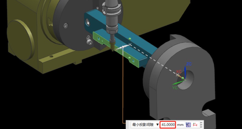
Next, rotate the A-axis 180 degrees in the negative direction. Same as the last step, we need to measure the machine position on the other side of the datum using the centering bar. Then, check the current relative Y value of the machine. For example, if we assume the Y value is “92mm”, the centering diameter is 10mm centering diameter, and the fixture datum to the rotary table is 41mm.
Step 4: Determine the Position of the Rotation Center in the Y-axis
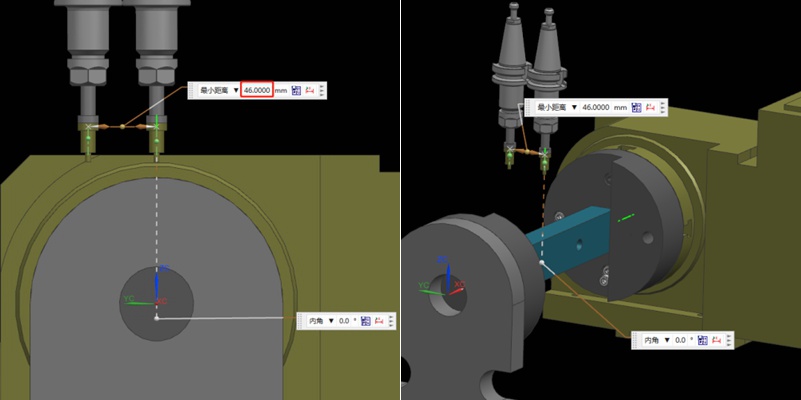
Referring to the values in the previous step, we can calculate that 92/2 = 46mm, so half of the Y value of 46mm. Then, we move the centering bar 46mm negatively towards the Y-axis.
As shown by the picture, the centering bar is now just aligned with the rotational axis of the rotary table. At the time, the position of the alignment point is the zero point of the Y value of the machine. In this way, we have completed half of the operation work.

Step 5: Find the Position of the Rotation Center in the Z-axis
Finding the Z value is relatively simple. After the rotary table returns to the A0 position, the zero point of the Z-axis of the rotary axis can be determined by moving down 41mm with the datum surface as the calculation base. This value is calculated using the formula “(92-10)/2”, where 92 is the Y-value found earlier and 10 is the diameter of the centering bar. By applying this formula, the Z value is determined.
Finally, the intersection of the Z and Y axis is the rotation center around the X axis. With these steps, we can determine the rotation center of the 4-axis rotary table.
Recomendaciones
Producción y fabricación de puentes: Etapas clave y ventajas
Adopting a final production process often involves numerous trials and failures, particularly during prototyping or low-volume production. Companies may temporarily select a production method until they are confident in their approach. Bridge production refers to this temporary strategy, enabling continued operations while a more reliable manufacturing process is developed. Understanding bridge production is crucial for enhancing product development and expediting operations. This article...

Types Of Milling Explained: Know All Milling Operations
Milling is inarguably the backbone of the manufacturing industry, playing a direct role in high-quality production in industries including aerospace, automotive, medical, and defense. Milling operations are highly versatile and capable of handling complex geometries with precision and speed. In this article, we will discuss the fundamentals of CNC milling and explain various milling operations, helping to choose the right milling type for your applications.Milling is a machining process t...

All You Need To Know Engineering Drawing And Its Elements
Drawing or painting a picture is a great technique to convey one’s thoughts. Within the broad concept of industrial design, engineering drawing or technical drawing is an essential skill for designers working with the production of real objects. Therefore, engineering drawing is arguably one of the fundamentals of engineering design that serves several critical purposes. It is a standard technical drawing carrying essential design information, a mode of communication between different eng...

Torneado Escalonado vs. Torneado Cónico: ¿En qué se diferencian?
Turning is a fundamental machining operation that has supported the manufacturing industry for centuries. It continues to evolve and is a core manufacturing technique to this day. This article will discuss two types of turning operations: step turning vs taper turning. We will explore the step process and taper turning process and explain their differences.Turning is essentially a cutting operation where a sharp cutting tool shapes a rotating workpiece by removing material from its surfa...

