Causas y soluciones de las marcas de herramientas en el mecanizado de metales
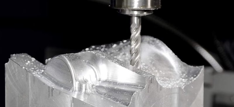
Precision metal parts are often manufactured using various precision machining technologies, with CNC machining being a common method. Usually, precision parts typically demand high standards for both dimensions and appearance.
Therefore, when using CNC machining metals such as aluminum and copper, the occurrence of tool marks and lines on the finished product’s surface is a concern. This article discusses the reasons that cause tool marks and lines during the machining of metal products. We also propose potential solutions.
Insufficient Clamping Force of Fixtures
Causes: Some cavity metal products need to use vacuum fixtures, and may struggle to generate sufficient suction due to the presence of surface irregularities, resulting in tool marks or lines.
Solution: To mitigate this, consider transitioning from simple vacuum suction to vacuum suction combined with pressure or lateral support. Alternatively, explore alternative fixture options based on specific part structures, tailoring the solution to the particular problem.
Process-related Factors
Causes: Certain product manufacturing processes may contribute to the issue. For instance, products like tablet PC rear shells undergo a sequence of machining steps involving punching side holes followed by CNC milling of the edges. This sequence can lead to noticeable tool marks when milling reaches the side-hole positions.
Solution: A common instance of this problem occurs when the aluminum alloy is chosen for electronic product shells. To resolve it, the process can be modified by replacing the side hole punching plus milling with only CNC milling. At the same time, ensuring consistent tool engagement and reducing uneven cutting when milling.
Inadequate Programming of Tool Path Engagement
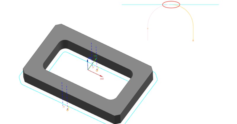
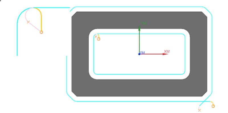
Causes: This issue commonly arises during the 2D contour machining phase of product production. Poorly designed tool path engagement in the CNC program, leaving traces at the entry and exit points of the tool.
Solution: To address the challenge of avoiding tool marks at entry and exit points, a typical approach involves introducing a slight overlap in tool engagement distance (approximately 0.2mm). This technique serves to circumvent potential inaccuracies in the machine’s lead screw precision.
While this strategy effectively prevents the formation of tool marks, it causes an element of repetitive machining when the material of the product is a soft metal. Consequently, this section may exhibit variations in texture and color compared to other areas.
Fish Scale Patterns on Flat Machined Surfaces
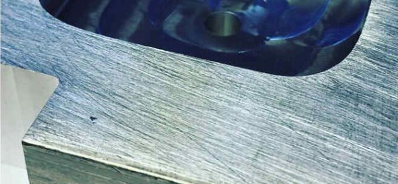
Causes: Fish scale or circular patterns appearing on the product’s flat surfaces. The cutting tools used for processing soft metals such as aluminum/copper are generally alloy material mills with 3 to 4 flutes. They have a hardness ranging from HRC55 to HRC65. These milling cutting tools are performed using the bottom edge of the tool, and the part surface may develop distinctive fish scale patterns, impacting its overall appearance.
Solution: Commonly observed in products with high flatness requirements and flat surfaces featuring recessed structures. A remedy is to switch to cutting tools made from synthetic diamond material, which helps achieve smoother surface finishes.
Aging and Wear of Equipment Components
Causes: The tools mark on the product surface is attributed to the aging and wear of the equipment’s spindle, bearings, and lead screw. Additionally, inadequate CNC system backlash parameters contribute to pronounced tool marks, particularly when machining rounded corners.
Solution: These issues stem from equipment-related factors and can be addressed by targeted maintenance and replacement.
Conclusion
Achieving an ideal surface in the CNC machining metals demands useful approaches. There are different methods to avoid tool marks and lines that involve a combination of equipment maintenance, fixture enhancements, process adjustments, and programming refinements. By understanding and rectifying these factors, manufacturers can ensure that precision components not only meet dimensional criteria but also exhibit the desired aesthetic qualities.
Recomendaciones
All You Need To Know Engineering Drawing And Its Elements
Drawing or painting a picture is a great technique to convey one’s thoughts. Within the broad concept of industrial design, engineering drawing or technical drawing is an essential skill for designers working with the production of real objects. Therefore, engineering drawing is arguably one of the fundamentals of engineering design that serves several critical purposes. It is a standard technical drawing carrying essential design information, a mode of communication between different eng...

Cost Of CNC Machining: What Affects & How to Save It?
CNC machining is a technique used to make precision parts and replicate amazing designs. There are a lot of advantages of CNC machining, such as increasing the speed of parts production. It also reduces human errors during manufacturing as it is being controlled by the computer. However, many people do not seem to understand the rationale behind its cost. The machine and material you use can affect the price. Today, many customers still struggle with CNC machining cost calculation. With t...

Tolerancia de ajuste a presión: Definición, prácticas y cálculo
La industria manufacturera está muy centrada en la precisión, donde hasta el más mínimo margen puede crear enormes diferencias en la calidad, el coste y la utilidad del producto. Este artículo aborda el tema del ajuste a presión, en el que unos pocos micrómetros de desviación dictan el criterio para el fallo de una pieza. Así pues, qué es el ajuste a presión y los factores que influyen en el tolerado del ajuste a presión, y presentamos un ejemplo de calculadora de ajuste a presión. También compartiremos algunos consejos clave a tener en cuenta al diseñar componentes para p...

How To Create A Prototype With Steps: An Expert Guide
A prototype is an early version or physical model of a product idea that manufacturers can test and refine before investing in mass production. It acts as a product template and provides a practical approach to understanding a product’s appearance and function before production. When developing a product, product teams create a product prototype to test the product’s usability, design, and performance, gather user feedback, identify potential issues in the early stages, and identify possib...

