All You Need To Know Engineering Drawing And Its Elements
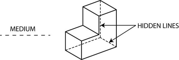
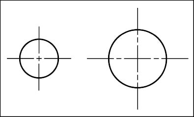
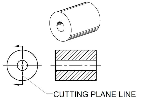
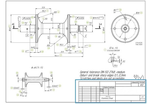
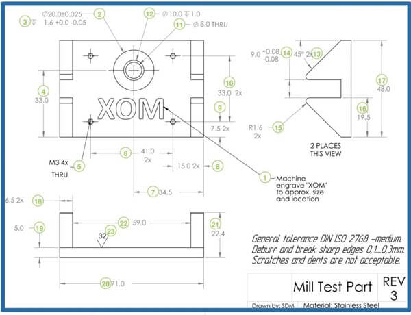
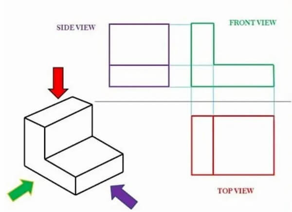
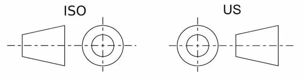
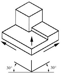
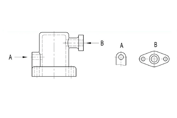
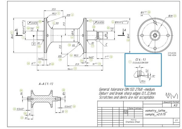
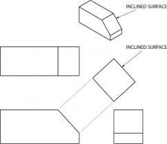
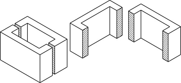
Engineering drawings are detailed documents with numerous key elements. These elements carry necessary information that contributes to the completeness and comprehensibility of the mechanical drawing. With each part of the engineering drawing having a well-defined purpose, it is good to know what it is to be able to create and read professional drawings. The first and foremost element in a technical drawing is the geometry of the part. The discussion above describes in detail how design engineers include geometry in engineering drawings through different types of views. The bulk of the drawing body is composed of engineering diagrams, and depending upon the complexity of the part, there can be multiple views of different types spanning several pages. One may gauge the importance of this element by the fact that all the drawing views in the previous section relate to part geometry one way or another. An engineering drawing doesn’t have equal lines. A part’s visible and concealed boundaries, centerlines, and other details can all be displayed using the various choices. The following are the types of lines. A drawing line, or a continuous line, is the most common. It’s a visual representation of an object’s physical boundaries. To put it another way, a continuous line is used to draw the real objects. Variations in line thickness are used; thicker lines are used on the outside contour and thinner lines are used on the inner contour. Lines that are not visible to the naked eye can reveal information that would otherwise be obscured by the designs. The length of an interior step in a turned part can be shown using hidden lines instead of a section or cutout view. Parts with holes and symmetrical features can be shown by using center lines. Symmetry can reduce the number of dimensions in a drawing and make it more visually appealing, making it easier for the reader to comprehend. Extension lines are used to describe the data being collected. Two arrowheads separate the extension lines on the dimension line from the measurement above (or inside, as shown in the image above). When a view is broken, break lines appear. In the case of a part that is 3000 mm long and 10 mm wide and has the same geometric qualities, a break-out provides all the information without taking up too much space. CNC machines necessitate complete views of the workpieces in order to cut them. Alternatively, the manufacturing engineer will have to re-create the entire part from the measurements alone. The cutting plane lines illustrate the path of the cutout in a cutout view. The A-A cutting line may be seen here bringing both types of holes into view. Besides geometry and lines, dimensions and tolerances are another important element of engineering drawing assembly. They provide exact information about the size and form of the design, putting the scope of the project into perspective for teams down the line. Typically, dimensions and tolerances appear side by side as the tolerance applies to the dimensions themselves. For example, a typical dimension may appear as in the example below. It communicates that the nominal dimension is 20.00 and that its allowable deviation (tolerance) can be +0.05 in the positive direction and 0.00 in the negative direction. Designs very frequently use engineering drawing symbols in technical drawings to indicate various things. While geometry and dimensions are necessary to communicate the design, there is still a great deal of information that cannot be expressed through them. For these, engineers use symbols. A common use of symbols is in Geometric Dimensioning & Tolerancing (GD&T), which primarily focuses on defining and tolerancing the form and size of drawing features. For example, there are symbols for entities such as cylindricity and parallelism, both of which are difficult to convey through lines or dimensions. Another common use is on welding joints. There are numerous types of welding joints with various specifications. Rather than writing a note for each joint, engineers use symbols for convenience. The title block is an essential part of any engineering drawing. Typically, it is a small table at the bottom right corner of the drawing, and it carries critical information regarding the identity and origin of the document. Some of the main elements are: The key elements of engineering drawing in the previous sections appear in every drawing. In addition to these, organizations may choose to add more information due to technical needs or convenience. A few examples of additional information may include: In large or complicated technical drawings, coordinates are commonly employed and positioned along the drawing’s boundaries. When discussing the drawing’s content, these points of reference serve as a guide. Now, let’s dig a bit deeper into what goes inside the drawing space of a technical drawing. Engineers communicate their design specifications through numerous types of engineering drawing views. Each view provides a different perspective, adding clarity and detail to the drawing. The main types of views in engineering diagrams are as follows: The orthographic view is the core of an engineering drawing’s content. A 2D representation of a three-dimensional object is called an orthographic view or orthographic projection. Thus, a 2D view must provide all the information necessary for the production of a part. Any length distortion is avoided with this representation. As the most common method for conveying all the necessary information, multiview drawings often include three views: It’s conceivable that a few extra views are required to display all of the information. Less is definitely more. Regionally, the views are a little different. Compare the US and ISO layouts by taking a look at this image. Drawing layouts in ISO and the United States are in direct opposition to one another. The one on the left is known as a first-angle projection. There is a top view, a front view, a side view, and so on in this arrangement. In Europe, the ISO standard is most commonly used. A third-angle projection may be seen to the right of the image. All of these images are arranged in chronological order. The United States and Canada are particularly fond of this arrangement. The figure above is an example of an isometric view. Isometric drawings depict three-dimensional objects. When compared to the front view, all vertical lines remain vertical, and parallel lines are depicted at a 30-degree angle. Vertical and parallel lines have the correct length. Using a ruler and the scaling of the picture, for example, you can simply measure the length of a paper drawing. Angled lines are not the same. It’s critical to know the difference between an isometric view and a perspective view. In art, perspective views depict an object as it appears to the human eye. Engineers do not rely on optical illusions but rather stick to the facts. A partial view is a view obtained by projecting a part of an object onto the basic projection plane. Use arrows with letters to indicate the part to be expressed and the direction of projection, and indicate the name of the view. The local view can be configured in the form of the basic view or configured and marked in the form of the configuration towards the view. As a callout or segment in other views, a detailed view shows the model in its entirety. The detail view often depicts the model at a much finer level of detail than the parent view does. An auxiliary view is an orthographic view for non-horizontal or non-vertical planes. It aids in the presentation of inclined surfaces without distortion. An oblique view is a view of an object projected into a plane not parallel to the basic projection plane. The oblique view is usually configured in the form of a view towards, with an arrow with a capital letter indicating the direction of projection, and the same letter marked above the corresponding oblique view. If necessary, a rotated configuration of the oblique view is allowed. The capital letter indicating the name of this view should be near the arrow end of the rotation symbol, and it is also permitted to mark the rotation angle after the letter. In actual production, the shape of the part is very varied, only the above views are not enough to express the internal and external shape and structure of the part clearly, for this reason, there are a variety of ways to express the shape of the structure of the part: sectional view, cross-sectional views, partial enlargement view, etc. You can better depict the interior of a complicated object, such as an automobile’s engine block, by sketching the object as it would appear if cut apart. In this manner, the sketch’s many hidden lines are erased. Sectioning is the practice of drawing an object’s interior structure by illustrating it as if it had been cut apart. Sectioning is a common feature of many industrial designs. Sectioning the block above results in blocks A and B, as shown. An object in a painting or sketch can be sectioned in any way you like, just like an apple. This type of section is called a full section when a cutting plane line passes completely through an object. Sectioning an object can be done whenever a closer look is necessary. This object has been cut into two halves, as you can see. When the part has a symmetrical plane, the graph projected on the projection plane perpendicular to the symmetrical plane can be bounded by the symmetrical centerline, half of which is drawn as a sectional view and the other half as a view. This sectional view is called a semi-sectional view. The semi-sectional view is used for symmetrical members whose internal and external structures need to be expressed. The dividing line of the semi-sectional view is drawn with a single dotted line. Due to the symmetry of the graph, the internal structure of the parts has been clearly expressed in the section, and no hidden lines are drawn in the view part. Views with broken-out sections can be used to reveal the model’s inner details by cutting away material at a predetermined depth. The broken-out part is defined by a closed profile, typically a spline. Users can enter a precise depth or reference a place in another view to specify a depth. With respect to an object’s cross-sectional area, the orthographic projection of that object’s cross-section is equal to its overall area. A cylinder of height h and radius r, for example, has when seen in an orthogonal direction and along its central axis. The use of partial views in technical drawing documentation makes it easier to provide the needed details on parts. A lot of the time, it’s easier to show more detail about a part when you use partial views of the part. Engineers often make the mistake of trying to incorporate all the information about each individual part in an assembly drawing. This can be avoided if you keep in mind that the goal of these technical drawings is to facilitate the assembly process. In order to accomplish this, you can utilize tools like section views, numbered pieces, general dimensions, cuts, and detail views (or close-ups). Regardless of the method of attachment, it should be apparent where each component goes and how it is attached. For your benefit, make sure the bill of materials has accurate information about part numbers, names, and quantities. All of this will help you design assembly drawings that will make your projects in the machine shop more efficient. Engineering drawing is a highly standardized field with numerous international standards in place to guide professionals across the globe. These standards apply to various aspects of technical drawings from the basics of engineering diagrams to engineering drawing symbols. The ASME Y14.5, Y14.3, and Y14.100 are arguably the most widely accepted standards defining good practices for geometric dimensioning and tolerancing (GD&T), projection views, and standardized frameworks for engineering drawings, respectively. Furthermore, the ISO 128 and ISO 129 standards cover critical information regarding line types, scales, projections, and tolerancing rules. Engineering design is a wide discipline, and it covers other areas apart from mechanical drawing, which is reflected in the fact that there are numerous kinds of engineering diagrams. This section gives an overview of some of these main types.
1. Geometry
2. Line Types
2.1 Continuous Lines
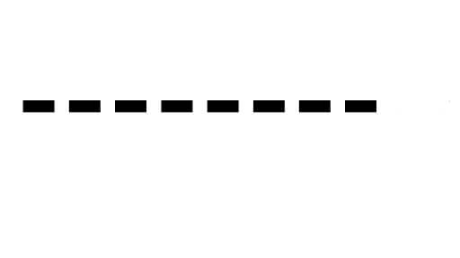
2.2 Hidden Lines
2.3 Center Lines
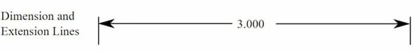
2.4 Dimension Lines
2.5 Broken View Lines
2.6 Cutting Plane Lines
3. Dimensions/Tolerances
4. Symbols
5. Title Block
6. Additional Information
7. Coordinates
Types Of Engineering Drawing Views
1. Orthographic View
2. Isometric View
3. Partial View
4. Detail View
5. Auxiliary View
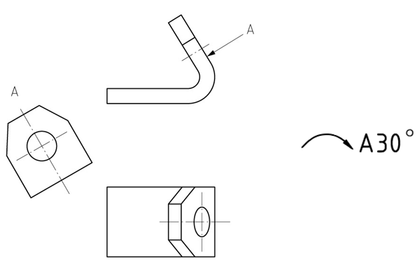
6. Oblique View
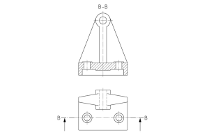
7. Sectional View
7.1 Full Sectioning
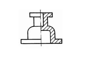
7.2 Semi-sectional View
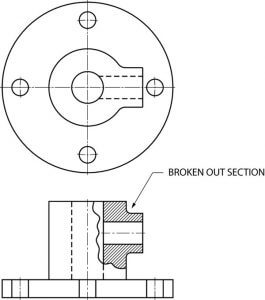
7.3 Broken-out Sections
8. Cross-sectional View
9. Partial enlargement View
10. Assembly Drawings
Common Standards For Engineering Drawings
Other Engineering Drawings
Recommandations
Causes et solutions pour les marques d'outils dans l'usinage des métaux
Les pièces métalliques de précision sont souvent fabriquées à l'aide de diverses technologies d'usinage de précision, l'usinage CNC étant une méthode courante. En général, les pièces de précision exigent des normes élevées en matière de dimensions et d'aspect. Par conséquent, lors de l'usinage CNC de métaux tels que l'aluminium et le cuivre, l'apparition de marques et de lignes d'outils sur la surface du produit fini est un problème. Cet article examine les raisons qui provoquent des marques et des lignes d'outil lors de l'usinage de produits métalliques....

Usinage CNC de l'acrylique : Tout ce que vous devez savoir Pièces usinées en acrylique
Aujourd'hui, nous allons nous pencher sur les processus de fabrication du polymère acrylique ou prototypage optique. Il s'agit de l'un des plastiques les plus répandus dans le monde et d'un concurrent important du verre et du polycarbonate. Étant donné que les pièces en acrylique sont utilisées dans de nombreux secteurs industriels, il semble judicieux de se pencher sur ses processus de fabrication, en particulier l'usinage CNC de l'acrylique, car c'est le processus qui est présent dans presque tous les types de production d'acrylique. Dans cet article, nous...

Comment éviter les collisions entre machines dans le processus d'usinage ?
Les collisions avec les machines ont toujours été un défi inévitable dans l'usinage des prototypes et des pièces. Les erreurs de l'opérateur, comme le fait de ne pas effectuer les réglages de l'outil, peuvent entraîner des collisions. Il en résultera des outils cassés, des pièces mises au rebut, des commandes à refaire et des matériaux à retraiter. En outre, en l'absence de dispositif de réglage automatique des outils, le réglage manuel des outils lors de l'entrée d'une erreur dans les données de la valeur Z peut également provoquer des collisions avec la machine. Dans cet article, nous partagerons nos expériences résumées pour vous aider à éviter ce problème. Avant de...

Types Of Milling Explained: Know All Milling Operations
Milling is inarguably the backbone of the manufacturing industry, playing a direct role in high-quality production in industries including aerospace, automotive, medical, and defense. Milling operations are highly versatile and capable of handling complex geometries with precision and speed. In this article, we will discuss the fundamentals of CNC milling and explain various milling operations, helping to choose the right milling type for your applications.Milling is a machining process t...

