4軸CNCマシンの操作時に回転中心を決定するには?
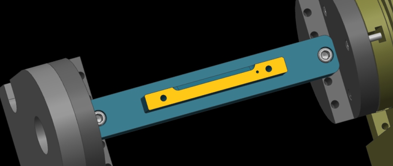
Here, we show a 4-axis rotary table that rotates around the X-axis of a machine tool, where the axis of rotation is called the A-axis. In a word, all we need to do is to determine the Y/Z coordinates of the center of rotation on the 4-axis machine.
In addition, the X coordinate values are determined by the placement of the product, so we won’t go into detail here. The following are the specific steps to determine the center of rotation.
Step 1: Calibrate the Fixture Reference Plane
Firstly, use the calibration table to calibrate the fixture datum plane (the yellow surface). Then, set the calibrated datum plane to the 0 degree position of the A-axis.
Step 2: Set the Fixture Datum Plane
After setting the datum plane, we need to rotate the A-axis 90 degrees positive. Then, use a centering bar to measure the machine position where the datum plane is located. In the relative coordinate setting, set the Y coordinate to “0”.
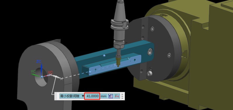
Step 3: Measure the Value of the Datum Plane
Next, rotate the A-axis 180 degrees in the negative direction. Same as the last step, we need to measure the machine position on the other side of the datum using the centering bar. Then, check the current relative Y value of the machine. For example, if we assume the Y value is “92mm”, the centering diameter is 10mm centering diameter, and the fixture datum to the rotary table is 41mm.
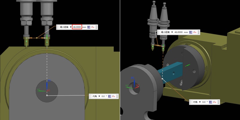
Step 4: Determine the Position of the Rotation Center in the Y-axis
Referring to the values in the previous step, we can calculate that 92/2 = 46mm, so half of the Y value of 46mm. Then, we move the centering bar 46mm negatively towards the Y-axis.
As shown by the picture, the centering bar is now just aligned with the rotational axis of the rotary table. At the time, the position of the alignment point is the zero point of the Y value of the machine. In this way, we have completed half of the operation work.

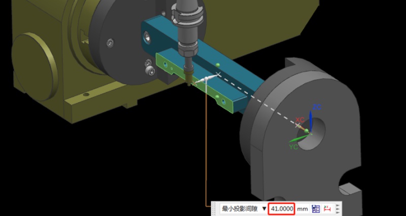
Step 5: Find the Position of the Rotation Center in the Z-axis
Finding the Z value is relatively simple. After the rotary table returns to the A0 position, the zero point of the Z-axis of the rotary axis can be determined by moving down 41mm with the datum surface as the calculation base. This value is calculated using the formula “(92-10)/2”, where 92 is the Y-value found earlier and 10 is the diameter of the centering bar. By applying this formula, the Z value is determined.
Finally, the intersection of the Z and Y axis is the rotation center around the X axis. With these steps, we can determine the rotation center of the 4-axis rotary table.
推薦の言葉
CNCアクリル加工:あなたが知る必要があるすべてはアクリルの部品を機械で造った
今日は、アクリルポリマーや光学プロトタイプの製造工程について見ていこう。アクリルポリマーは、世界中で最も普及しているプラスチックの一つであり、ガラスやポリカーボネートと競合しています。アクリル部品は多くの産業分野で使用されているため、その製造工程、特にCNCアクリル機械加工について調べるのは良い考えだと思われる。この記事では、CNCアクリル加工について説明する。

CNC加工中の大型・薄肉シェル部品の反りや変形を防ぐには?
Large, thin-walled shell parts are easy to warp and deform during machining. In this article, we will introduce a heat sink case of large and thin-walled parts to discuss the problems in the regular machining process. In addition, we also provide an optimized process and fixture solution. Let’s get to it! The case is about a shell part made of AL6061-T6 material. Here are its exact dimensions. Overall Dimension: 455*261.5*12.5mmSupport Wall Thickness: 2.5mmHeat Sink Thickness: 1.5mmHe...

SFMとは?機械加工における1分あたりの表面粗さの完全ガイド
SFMとは、CNCマシニングにおける1分あたりの表面粗さ(Surface Feet per Minute)を意味し、切削工具がワークピースを移動する速さを測定する。単位はフィート/分。SFMは、工具または工作物の直径と主軸回転数(RPM)を組み合わせたものです。直径が大きいほど、または回転数が高いほど、SFMは高くなる。マシニストは、材料に最適な切削速度を決定するために、サーフェスフィート/分を使用します。材料によって、最適な性能を発揮するための推奨SFM値があります。例えば、303アニールステンレス鋼のSFM値は...

CNC加工のコスト:何が影響し、どのようにそれを保存するには?
CNCマシニングは、精密部品を作ったり、素晴らしいデザインを再現するために使われる技術です。CNCマシニングには、部品製造のスピードを上げるなど、多くの利点があります。また、コンピューターによって制御されるため、製造中の人的ミスを減らすこともできる。しかし、多くの人はそのコストの根拠を理解していないようだ。使用する機械や材料が価格に影響することもある。今日でも、多くの顧客がCNC加工のコスト計算に頭を悩ませている。CNCマシニングセンタを使用することで

