전체 방송국 검색 알루미늄 부품 스물다섯

CNC 가공 중 크고 얇은 쉘 부품의 뒤틀림과 변형을 방지하는 방법은 무엇입니까?

사례 연구 리소스 128

Large, thin-walled shell parts are easy to warp and deform during machining. In this article, we will introduce a heat sink case of large and thin-walled parts to discuss the problems in the regular machining process. In addition, we also provide an optimized process and fixture solution. Let’s get to it!

dimensions of the shell structure

The case is about a shell part made of AL6061-T6 material. Here are its exact dimensions.

Overall Dimension: 455*261.5*12.5mm
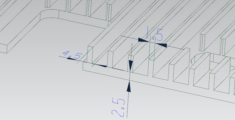
Support Wall Thickness: 2.5mm
Heat Sink Thickness: 1.5mm
Heat Sink Spacing: 4.5mm


Practice and Challenges in Different Process Routes

During CNC machining, these thin-walled shell structures often cause a range of problems, such as warping and deformation. To overcome these issues, we try to offer serval process route options. However, there are still some exact issues for each process. Here are the details.


Process Route 1

In process 1, we start by machining the reverse side (inner side) of the workpiece and then use plaster to fill in the hollowed-out areas. Next, letting the reverse side be a reference, we use glue and double-sided tape to fix the reference side in place in order to machine the front side.

However, there are some problems with this method. Due to the large hollowing backfilled area on the reverse side, the glue and double-sided tape are not sufficiently secure the workpiece. It leads to warping in the middle of the workpiece and more material removal in the process (called overcutting). In addition, the lack of stability of the workpiece also leads to low processing efficiency and poor surface knife pattern.

thinwall cnc part


Process Route 2

In process 2, we change the order of machining. We start with the underside (the side where the heat is dissipated) and then use the plaster backfilling of the hollow area. Next, letting the front side as a reference, we use glue and double-sided tape to fix the reference side so that we could work the reverse side.

However, the problem with this process is similar to process route 1, except that the issue is shifted to the reverse side (inner side). Again, when the reverse side has a large hollowing backfill area, the use of glue and double-sided tape do not provide high stability to the workpiece, resulting in warping.


Process Route 3

In process 3, we consider using the machining sequence of process 1 or process 2. Then in the second fastening process, use a press plate to hold the workpiece by pressing down on the perimeter.

However, due to the large product area, the platen is only able to cover the perimeter area and could not fully fix the central area of the workpiece.

On the one hand, this results in the center area of the workpiece still appearing from warping and deformation, which in turn leads to overcutting in the center area of the product. On the other hand, this machining method will make the thin-walled CNC shell parts too weak.


Process Route 4

In process 4, we machine the reverse side (inner side) first and then use a vacuum chuck to attach the machined reverse plane in order to work the front side.

However, in the case of the thin-walled shell part, there are concave and convex structures on the reverse side of the workpiece that we need to avoid when using vacuum suction. But this will create a new problem, the avoided areas lose their suction power, especially in the four corner areas on the circumference of the largest profile.

As these non-absorbed areas correspond to the front side (the machined surface at this point), the cutting tool bounce could occur, resulting in a vibrating tool pattern. Therefore, this method can have a negative impact on the quality of the machining and the surface finish.


Optimized Process Route and Fixture Solution

In order to solve the above problems, we propose the following optimized process and fixture solutions.


Pre-machining Screw Through-holes

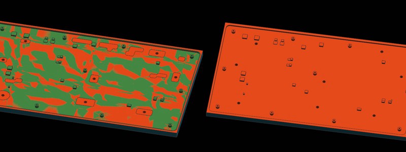
Firstly, we improved the process route. With the new solution, we process the reverse side (inner side) first and pre-machine the screw through-hole in some areas that will eventually be hollowed out. The purpose of this is to provide a better fixing and positioning method in the subsequent machining steps.


Circle the Area to be Machined

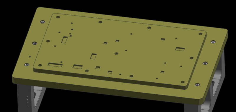
Next, we use the machined planes on the reverse side (inner side) as a machining reference. At the same time, we secure the workpiece by passing the screw through the over-hole from the previous process and locking it to the fixture plate. Then circle the area where the screw is locked as the area to be machined.

machining areas


Sequential Machining with Platen

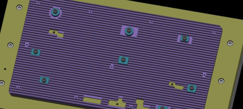
During the machining process, we first process the areas other than the area to be machined. Once these areas have been machined, we place the platen on the machined area (the platen needs to be covered with glue to prevent crushing of the machined surface). We then remove the screws used in step 2 and continue machining the areas to be machined until the entire product is finished.

With this optimized process and fixture solution, we can hold the thin-walled CNC shell part better and avoid problems such as warping, distortion, and overcutting. The mounted screws allow the fixture plate to be tightly attached to the workpiece, providing reliable positioning and support. In addition, the use of a press plate to apply pressure on the machined area helps to keep the workpiece stable.


In-depth Analysis: How to Avoid Warping and Deformation?

Achieving successful machining of large and thin-walled shell structures requires an analysis of the specific problems in the machining process. Let’s take a closer look at how these challenges can be effectively overcome.


Pre-machining Inner Side

In the first machining step (machining the inner side), the material is a solid piece of material with high strength. Therefore, the workpiece does not suffer from machining anomalies such as deformation and warping during this process. This ensures stability and precision when machining the first clamp.


Use the Locking and Pressing Method

For the second step (machining where the heat sink is located), we use a locking and pressing method of clamping. This ensures that the clamping force is high and evenly distributed on the supporting reference plane. This clamping makes the product stable and does not warp during the entire process.


Alternative Solution: Without Hollow Structure

However, we sometimes meet situations where it is not possible to make a screw through-hole without a hollow structure. Here is an alternative solution.

We can pre-design some pillars during the machining of the reverse side and then tapping on them. During the next machining process, we have the screw pass through the reverse side of the fixture and lock the workpiece, and then carry out the machining of the second plane (the side where the heat is dissipated). In this way, we can complete the second machining step in a single pass without having to change the plate in the middle. Finally, we add a triple clamping step and remove the process pillars to complete the process.

In conclusion, by optimizing the process and fixture solution, we can successfully solve the problem of warping and deformation of large, thin shell parts during CNC machining. This not only ensures machining quality and efficiency but also improves the stability and surface quality of the product.

가공 공정에서 기계 충돌을 피하는 방법은?

기계 충돌은 프로토타입 및 부품 가공에서 항상 피할 수 없는 과제였습니다. 공구 설정 실패와 같은 작업자 오류는 충돌로 이어질 수 있습니다. 이는 공구 파손, 공작물 폐기, 재료 재주문 및 재가공으로 이어질 수 있습니다. 또한 자동 공구 세터가 없는 경우 Z값 데이터 오류 입력 시 수동 공구 설정도 기계 충돌을 일으킬 수 있습니다. 이 기사에서는 이러한 문제를 방지하는 데 도움이 되는 요약된 경험을 공유합니다. Bef...

기계 가공에서 기계 충돌을 피하는 방법...

4축 CNC 기계를 작동할 때 로터리의 회전 중심을 결정하는 방법은 무엇입니까?

오늘날 4축 로터리 테이블은 기계 공장에서 흔히 볼 수 있는 장비입니다. 하나의 좌표에서 여러 면의 가공을 완료하려면 프로그래밍 좌표가 로터리 테이블의 좌표와 동기화되어야 합니다. 이 기사에서는 4축 로터리 테이블의 회전 중심을 결정하는 방법을 공유하겠습니다.여기서는 공작 기계의 X축을 중심으로 회전하는 4축 로터리 테이블을 보여주며, 여기서 회전 축을 A축이라고 합니다. 한마디로...

로타리의 회전 중심을 결정하는 방법 ...

공정 경로와 픽스처를 설계하여 다면체 알루미늄 부품을 가공하는 방법은 무엇입니까?

가공 및 제조 분야에서는 생산 효율성을 개선하기 위해 적절한 가공 전략을 선택하는 것이 중요합니다. 일반적으로 다면체 가공 부품은 형상이 복잡하고 공차 요구 사항이 엄격합니다. 따라서 이러한 부품 가공에 적합한 가공 경로를 선택하려면 종합적인 고려가 필요합니다. 이 기사에서 워싱은 다면체 알루미늄 부품의 다양한 공정 경로에 대한 분석을 제공하고 3+2 축 CNC 가공과 ...

다면체 알루미늄 부품을 가공하는 방법 ...

가공 수당 설명: 계산 및 중요 사항

가공 공차는 제조의 기본 개념입니다. 이는 항공우주, 방위, 의료 등 다양한 산업에서 치수 정확도, 표면 품질, 신뢰할 수 있고 기능적인 부품 생산을 보장하는 CNC 정밀 가공의 일반적인 엔지니어링 관행입니다. 이 글에서는 가공 공차란 무엇인가라는 질문에 답하고자 합니다. 가공 공차의 개념에 대해 자세히 살펴보고 기계 가공자가 가공 공차를 남기는 이유에 대해 논의합니다....

가공 수당 설명: 그 계산 ...
더 확장하세요!