4축 CNC 기계를 작동할 때 로터리의 회전 중심을 결정하는 방법은 무엇입니까?
Here, we show a 4-axis rotary table that rotates around the X-axis of a machine tool, where the axis of rotation is called the A-axis. In a word, all we need to do is to determine the Y/Z coordinates of the center of rotation on the 4-axis machine.
In addition, the X coordinate values are determined by the placement of the product, so we won’t go into detail here. The following are the specific steps to determine the center of rotation.
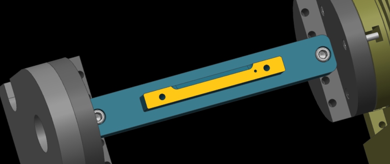
Step 1: Calibrate the Fixture Reference Plane
Firstly, use the calibration table to calibrate the fixture datum plane (the yellow surface). Then, set the calibrated datum plane to the 0 degree position of the A-axis.
Step 2: Set the Fixture Datum Plane
After setting the datum plane, we need to rotate the A-axis 90 degrees positive. Then, use a centering bar to measure the machine position where the datum plane is located. In the relative coordinate setting, set the Y coordinate to “0”.
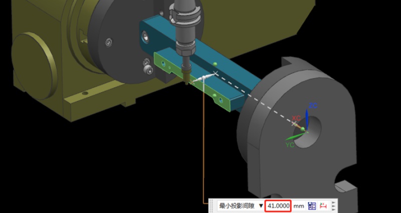
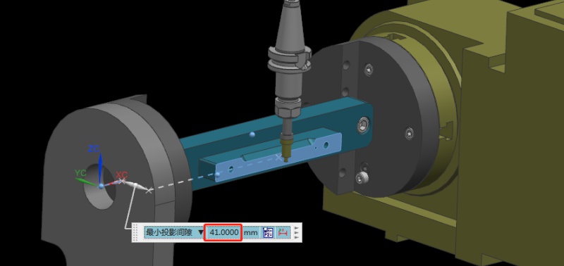
Step 3: Measure the Value of the Datum Plane
Next, rotate the A-axis 180 degrees in the negative direction. Same as the last step, we need to measure the machine position on the other side of the datum using the centering bar. Then, check the current relative Y value of the machine. For example, if we assume the Y value is “92mm”, the centering diameter is 10mm centering diameter, and the fixture datum to the rotary table is 41mm.
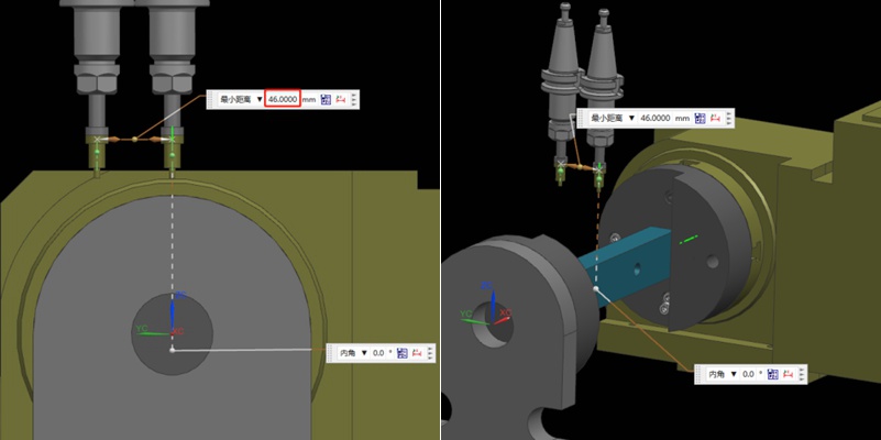
Step 4: Determine the Position of the Rotation Center in the Y-axis
Referring to the values in the previous step, we can calculate that 92/2 = 46mm, so half of the Y value of 46mm. Then, we move the centering bar 46mm negatively towards the Y-axis.
As shown by the picture, the centering bar is now just aligned with the rotational axis of the rotary table. At the time, the position of the alignment point is the zero point of the Y value of the machine. In this way, we have completed half of the operation work.

Step 5: Find the Position of the Rotation Center in the Z-axis
Finding the Z value is relatively simple. After the rotary table returns to the A0 position, the zero point of the Z-axis of the rotary axis can be determined by moving down 41mm with the datum surface as the calculation base. This value is calculated using the formula “(92-10)/2”, where 92 is the Y-value found earlier and 10 is the diameter of the centering bar. By applying this formula, the Z value is determined.
Finally, the intersection of the Z and Y axis is the rotation center around the X axis. With these steps, we can determine the rotation center of the 4-axis rotary table.
권장 사항
금속 가공 시 공구 마크의 원인과 해결 방법
정밀 금속 부품은 다양한 정밀 가공 기술을 사용하여 제조되는 경우가 많으며, CNC 가공이 일반적인 방법입니다. 일반적으로 정밀 부품은 일반적으로 치수와 외관 모두에 대해 높은 기준을 요구합니다. 따라서 알루미늄 및 구리와 같은 금속을 CNC 가공할 때 완제품 표면에 공구 자국과 선이 발생하는 것이 우려됩니다. 이 문서에서는 금속 제품 가공 중 공구 자국과 선이 발생하는 이유에 대해 설명합니다....

가공 수당 설명: 계산 및 중요 사항
가공 공차는 제조의 기본 개념입니다. 이는 항공우주, 방위, 의료 등 다양한 산업에서 치수 정확도, 표면 품질, 신뢰할 수 있고 기능적인 부품 생산을 보장하는 CNC 정밀 가공의 일반적인 엔지니어링 관행입니다. 이 글에서는 가공 공차란 무엇인가라는 질문에 답하고자 합니다. 가공 공차의 개념에 대해 자세히 살펴보고 기계 가공자가 가공 공차를 남기는 이유에 대해 논의합니다....

How To Create A Prototype With Steps: An Expert Guide
A prototype is an early version or physical model of a product idea that manufacturers can test and refine before investing in mass production. It acts as a product template and provides a practical approach to understanding a product’s appearance and function before production. When developing a product, product teams create a product prototype to test the product’s usability, design, and performance, gather user feedback, identify potential issues in the early stages, and identify possib...

브리지 생산 및 제조: 주요 단계 및 이점
최종 생산 공정을 채택하려면 특히 프로토타입 제작이나 소량 생산 과정에서 수많은 시행착오와 실패가 수반되는 경우가 많습니다. 기업은 접근 방식에 확신을 가질 때까지 일시적으로 생산 방법을 선택할 수 있습니다. 브리지 생산은 이러한 임시적인 전략을 말하며, 보다 안정적인 제조 프로세스를 개발하는 동안 지속적인 운영을 가능하게 합니다. 브리지 생산을 이해하는 것은 제품 개발을 개선하고 운영을 가속화하기 위해 매우 중요합니다. 이 문서...

