Zoeken in het hele station Aluminium Onderdelen twentytwentyfive

Hoe vervorming en kromtrekken in grote en dunwandige onderdelen te voorkomen tijdens CNC-bewerking?

Casestudies Hulpmiddelen 105

Large, thin-walled shell parts are easy to warp and deform during machining. In this article, we will introduce a heat sink case of large and thin-walled parts to discuss the problems in the regular machining process. In addition, we also provide an optimized process and fixture solution. Let’s get to it!

dimensions of the shell structure

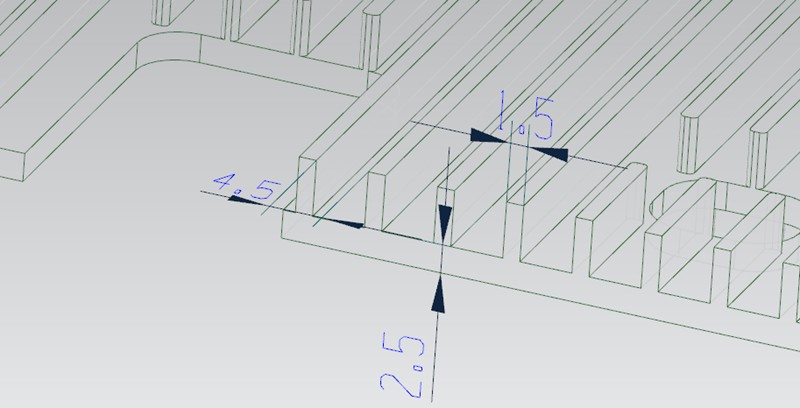
The case is about a shell part made of AL6061-T6 material. Here are its exact dimensions.

Overall Dimension: 455*261.5*12.5mm
Support Wall Thickness: 2.5mm
Heat Sink Thickness: 1.5mm
Heat Sink Spacing: 4.5mm


Practice and Challenges in Different Process Routes

During CNC machining, these thin-walled shell structures often cause a range of problems, such as warping and deformation. To overcome these issues, we try to offer serval process route options. However, there are still some exact issues for each process. Here are the details.


Process Route 1

In process 1, we start by machining the reverse side (inner side) of the workpiece and then use plaster to fill in the hollowed-out areas. Next, letting the reverse side be a reference, we use glue and double-sided tape to fix the reference side in place in order to machine the front side.

However, there are some problems with this method. Due to the large hollowing backfilled area on the reverse side, the glue and double-sided tape are not sufficiently secure the workpiece. It leads to warping in the middle of the workpiece and more material removal in the process (called overcutting). In addition, the lack of stability of the workpiece also leads to low processing efficiency and poor surface knife pattern.

thinwall cnc part


Process Route 2

In process 2, we change the order of machining. We start with the underside (the side where the heat is dissipated) and then use the plaster backfilling of the hollow area. Next, letting the front side as a reference, we use glue and double-sided tape to fix the reference side so that we could work the reverse side.

However, the problem with this process is similar to process route 1, except that the issue is shifted to the reverse side (inner side). Again, when the reverse side has a large hollowing backfill area, the use of glue and double-sided tape do not provide high stability to the workpiece, resulting in warping.


Process Route 3

In process 3, we consider using the machining sequence of process 1 or process 2. Then in the second fastening process, use a press plate to hold the workpiece by pressing down on the perimeter.

However, due to the large product area, the platen is only able to cover the perimeter area and could not fully fix the central area of the workpiece.

On the one hand, this results in the center area of the workpiece still appearing from warping and deformation, which in turn leads to overcutting in the center area of the product. On the other hand, this machining method will make the thin-walled CNC shell parts too weak.


Process Route 4

In process 4, we machine the reverse side (inner side) first and then use a vacuum chuck to attach the machined reverse plane in order to work the front side.

However, in the case of the thin-walled shell part, there are concave and convex structures on the reverse side of the workpiece that we need to avoid when using vacuum suction. But this will create a new problem, the avoided areas lose their suction power, especially in the four corner areas on the circumference of the largest profile.

As these non-absorbed areas correspond to the front side (the machined surface at this point), the cutting tool bounce could occur, resulting in a vibrating tool pattern. Therefore, this method can have a negative impact on the quality of the machining and the surface finish.


Optimized Process Route and Fixture Solution

In order to solve the above problems, we propose the following optimized process and fixture solutions.


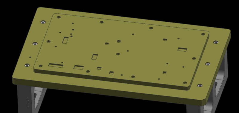
Pre-machining Screw Through-holes

Firstly, we improved the process route. With the new solution, we process the reverse side (inner side) first and pre-machine the screw through-hole in some areas that will eventually be hollowed out. The purpose of this is to provide a better fixing and positioning method in the subsequent machining steps.


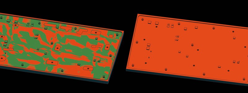
Circle the Area to be Machined

Next, we use the machined planes on the reverse side (inner side) as a machining reference. At the same time, we secure the workpiece by passing the screw through the over-hole from the previous process and locking it to the fixture plate. Then circle the area where the screw is locked as the area to be machined.

machining areas


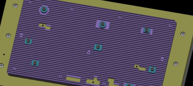
Sequential Machining with Platen

During the machining process, we first process the areas other than the area to be machined. Once these areas have been machined, we place the platen on the machined area (the platen needs to be covered with glue to prevent crushing of the machined surface). We then remove the screws used in step 2 and continue machining the areas to be machined until the entire product is finished.

With this optimized process and fixture solution, we can hold the thin-walled CNC shell part better and avoid problems such as warping, distortion, and overcutting. The mounted screws allow the fixture plate to be tightly attached to the workpiece, providing reliable positioning and support. In addition, the use of a press plate to apply pressure on the machined area helps to keep the workpiece stable.


In-depth Analysis: How to Avoid Warping and Deformation?

Achieving successful machining of large and thin-walled shell structures requires an analysis of the specific problems in the machining process. Let’s take a closer look at how these challenges can be effectively overcome.


Pre-machining Inner Side

In the first machining step (machining the inner side), the material is a solid piece of material with high strength. Therefore, the workpiece does not suffer from machining anomalies such as deformation and warping during this process. This ensures stability and precision when machining the first clamp.


Use the Locking and Pressing Method

For the second step (machining where the heat sink is located), we use a locking and pressing method of clamping. This ensures that the clamping force is high and evenly distributed on the supporting reference plane. This clamping makes the product stable and does not warp during the entire process.


Alternative Solution: Without Hollow Structure

However, we sometimes meet situations where it is not possible to make a screw through-hole without a hollow structure. Here is an alternative solution.

We can pre-design some pillars during the machining of the reverse side and then tapping on them. During the next machining process, we have the screw pass through the reverse side of the fixture and lock the workpiece, and then carry out the machining of the second plane (the side where the heat is dissipated). In this way, we can complete the second machining step in a single pass without having to change the plate in the middle. Finally, we add a triple clamping step and remove the process pillars to complete the process.

In conclusion, by optimizing the process and fixture solution, we can successfully solve the problem of warping and deformation of large, thin shell parts during CNC machining. This not only ensures machining quality and efficiency but also improves the stability and surface quality of the product.

CNC Acrylic Machining: All You Need To Know Machined Acrylic Parts

Today we are going to look at the manufacturing processes of acrylic polymer or optical prototyping. It is one of the most widespread plastics all over the world and a prominent competitor to glass and polycarbonate. Due to the fact that acrylic parts are used in a lot of industry areas, it seems a good idea to look into its manufacturing processes, specifically CNC acrylic machining since that is the process that is present in almost any kind of acrylic production. In this article, we wi...

CNC Acrylic Machining: All You Need To Know Mac...

Oorzaken en oplossingen voor gereedschapsmarkeringen bij het verspanen van metaal

Precision metal parts are often manufactured using various precision machining technologies, with CNC machining being a common method. Usually, precision parts typically demand high standards for both dimensions and appearance. Therefore, when using CNC machining metals such as aluminum and copper, the occurrence of tool marks and lines on the finished product’s surface is a concern. This article discusses the reasons that cause tool marks and lines during the machining of metal products....

Oorzaken en oplossingen voor gereedschapsstrepen in...

Step Turning vs. Taper Turning: Wat zijn de verschillen?

Turning is a fundamental machining operation that has supported the manufacturing industry for centuries. It continues to evolve and is a core manufacturing technique to this day. This article will discuss two types of turning operations: step turning vs taper turning. We will explore the step process and taper turning process and explain their differences.Turning is essentially a cutting operation where a sharp cutting tool shapes a rotating workpiece by removing material from its surfa...

Stapsgewijs draaien vs. conisch draaien: Wat zijn de verschillen ...

Hoe machinebotsingen tijdens het machinaal bewerken vermijden?

Machine collision has always been an inevitable challenge in prototype and part machining. Operator errors, such as failing to perform tool settings, can lead to crashes. It will result in broken tools, scrapped workpieces, and reordering and reprocessing materials. In addition, without the automatic tool setter, manual tool setting when entering Z-value data error can also cause machine collision. In this article, we will share our summarized experiences to help you avoid this issue. Bef...

Hoe machinebotsingen vermijden bij...
Meer uitbreiden!