Jak określić środek obrotu podczas obsługi 4-osiowej maszyny CNC?
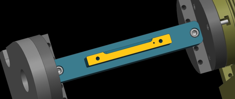
Here, we show a 4-axis rotary table that rotates around the X-axis of a machine tool, where the axis of rotation is called the A-axis. In a word, all we need to do is to determine the Y/Z coordinates of the center of rotation on the 4-axis machine.
In addition, the X coordinate values are determined by the placement of the product, so we won’t go into detail here. The following are the specific steps to determine the center of rotation.
Step 1: Calibrate the Fixture Reference Plane
Firstly, use the calibration table to calibrate the fixture datum plane (the yellow surface). Then, set the calibrated datum plane to the 0 degree position of the A-axis.
Step 2: Set the Fixture Datum Plane
After setting the datum plane, we need to rotate the A-axis 90 degrees positive. Then, use a centering bar to measure the machine position where the datum plane is located. In the relative coordinate setting, set the Y coordinate to “0”.
Step 3: Measure the Value of the Datum Plane
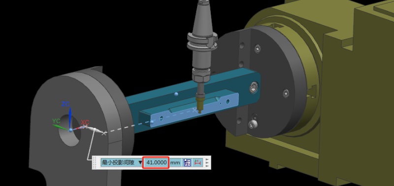
Next, rotate the A-axis 180 degrees in the negative direction. Same as the last step, we need to measure the machine position on the other side of the datum using the centering bar. Then, check the current relative Y value of the machine. For example, if we assume the Y value is “92mm”, the centering diameter is 10mm centering diameter, and the fixture datum to the rotary table is 41mm.
Step 4: Determine the Position of the Rotation Center in the Y-axis
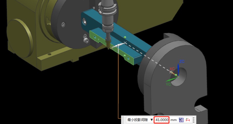
Referring to the values in the previous step, we can calculate that 92/2 = 46mm, so half of the Y value of 46mm. Then, we move the centering bar 46mm negatively towards the Y-axis.
As shown by the picture, the centering bar is now just aligned with the rotational axis of the rotary table. At the time, the position of the alignment point is the zero point of the Y value of the machine. In this way, we have completed half of the operation work.

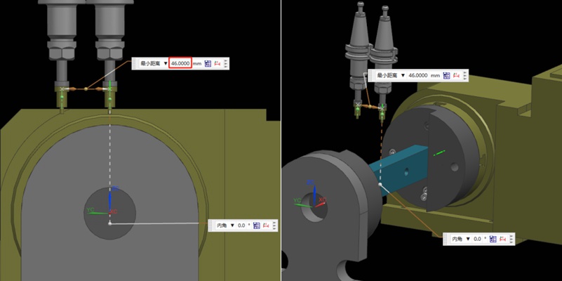
Step 5: Find the Position of the Rotation Center in the Z-axis
Finding the Z value is relatively simple. After the rotary table returns to the A0 position, the zero point of the Z-axis of the rotary axis can be determined by moving down 41mm with the datum surface as the calculation base. This value is calculated using the formula “(92-10)/2”, where 92 is the Y-value found earlier and 10 is the diameter of the centering bar. By applying this formula, the Z value is determined.
Finally, the intersection of the Z and Y axis is the rotation center around the X axis. With these steps, we can determine the rotation center of the 4-axis rotary table.
Recommendations
Jak uniknąć kolizji maszyn w procesie obróbki?
Machine collision has always been an inevitable challenge in prototype and part machining. Operator errors, such as failing to perform tool settings, can lead to crashes. It will result in broken tools, scrapped workpieces, and reordering and reprocessing materials. In addition, without the automatic tool setter, manual tool setting when entering Z-value data error can also cause machine collision. In this article, we will share our summarized experiences to help you avoid this issue. Bef...

Toczenie stopniowe a toczenie stożkowe: Jakie są różnice?
Turning is a fundamental machining operation that has supported the manufacturing industry for centuries. It continues to evolve and is a core manufacturing technique to this day. This article will discuss two types of turning operations: step turning vs taper turning. We will explore the step process and taper turning process and explain their differences.Turning is essentially a cutting operation where a sharp cutting tool shapes a rotating workpiece by removing material from its surfa...

Jak zapobiegać wypaczeniom i deformacjom dużych i cienkościennych części podczas obróbki CNC?
Large, thin-walled shell parts are easy to warp and deform during machining. In this article, we will introduce a heat sink case of large and thin-walled parts to discuss the problems in the regular machining process. In addition, we also provide an optimized process and fixture solution. Let’s get to it! The case is about a shell part made of AL6061-T6 material. Here are its exact dimensions. Overall Dimension: 455*261.5*12.5mmSupport Wall Thickness: 2.5mmHeat Sink Thickness: 1.5mmHe...

Press Fit Tolerance: Defination, Practices, and Calculation
The manufacturing industry is highly precision-centric, where even the slightest of margins can create huge differences in product quality, cost, and utility. This article discusses the topic of press fitting, where a few micrometers of deviation dictates the criterion for part failure. So, what is press fit and, the factors influencing press fit tolerancing, and present an example of a press fit calculator. We will also share some key tips to keep in mind while designing components for p...

