Como determinar o centro de rotação do Rotary ao operar uma máquina CNC de 4 eixos?
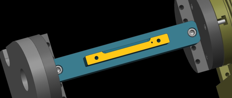
Here, we show a 4-axis rotary table that rotates around the X-axis of a machine tool, where the axis of rotation is called the A-axis. In a word, all we need to do is to determine the Y/Z coordinates of the center of rotation on the 4-axis machine.
In addition, the X coordinate values are determined by the placement of the product, so we won’t go into detail here. The following are the specific steps to determine the center of rotation.
Step 1: Calibrate the Fixture Reference Plane
Firstly, use the calibration table to calibrate the fixture datum plane (the yellow surface). Then, set the calibrated datum plane to the 0 degree position of the A-axis.
Step 2: Set the Fixture Datum Plane
After setting the datum plane, we need to rotate the A-axis 90 degrees positive. Then, use a centering bar to measure the machine position where the datum plane is located. In the relative coordinate setting, set the Y coordinate to “0”.
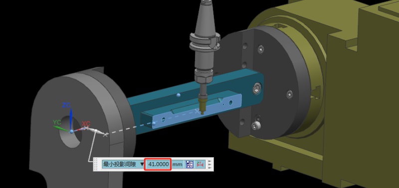
Step 3: Measure the Value of the Datum Plane
Next, rotate the A-axis 180 degrees in the negative direction. Same as the last step, we need to measure the machine position on the other side of the datum using the centering bar. Then, check the current relative Y value of the machine. For example, if we assume the Y value is “92mm”, the centering diameter is 10mm centering diameter, and the fixture datum to the rotary table is 41mm.
Step 4: Determine the Position of the Rotation Center in the Y-axis
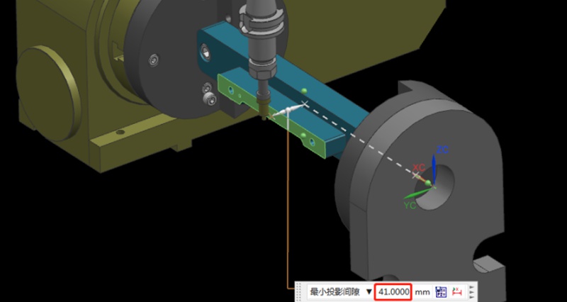
Referring to the values in the previous step, we can calculate that 92/2 = 46mm, so half of the Y value of 46mm. Then, we move the centering bar 46mm negatively towards the Y-axis.
As shown by the picture, the centering bar is now just aligned with the rotational axis of the rotary table. At the time, the position of the alignment point is the zero point of the Y value of the machine. In this way, we have completed half of the operation work.

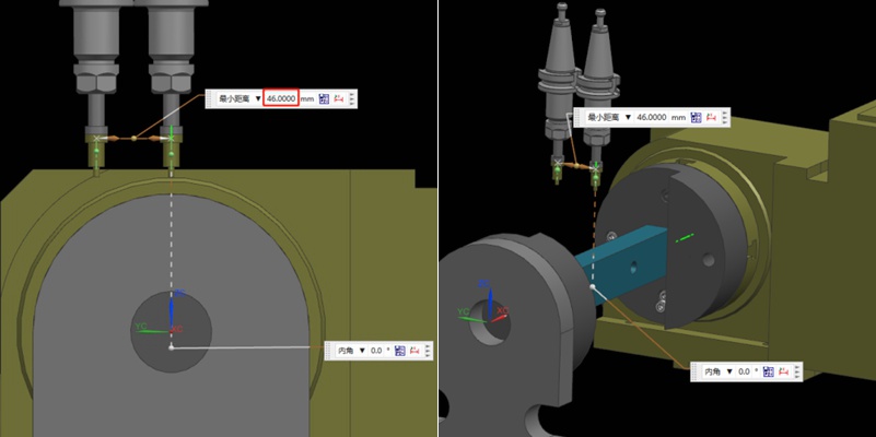
Step 5: Find the Position of the Rotation Center in the Z-axis
Finding the Z value is relatively simple. After the rotary table returns to the A0 position, the zero point of the Z-axis of the rotary axis can be determined by moving down 41mm with the datum surface as the calculation base. This value is calculated using the formula “(92-10)/2”, where 92 is the Y-value found earlier and 10 is the diameter of the centering bar. By applying this formula, the Z value is determined.
Finally, the intersection of the Z and Y axis is the rotation center around the X axis. With these steps, we can determine the rotation center of the 4-axis rotary table.
Recomendações
Como maquinar peças de alumínio poliédricas através da conceção de percursos de processo e de dispositivos de fixação?
No domínio da maquinagem e do fabrico, a seleção da estratégia de maquinagem adequada é importante para melhorar a eficiência da produção. Em geral, as peças maquinadas poliédricas têm geometrias complexas e requisitos de tolerância apertados. Assim, a escolha de uma rota de processamento adequada para maquinar essas peças requer considerações abrangentes. Neste artigo, a Washxing fornece uma análise de diferentes rotas de processamento para peças de alumínio poliédricas e compara a maquinação CNC de 3+2 eixos com a...

Como evitar a colisão de máquinas no processo de maquinagem?
A colisão de máquinas sempre foi um desafio inevitável na maquinação de protótipos e peças. Erros do operador, como não efetuar as definições da ferramenta, podem levar a colisões. Isto resultará em ferramentas partidas, peças de trabalho sucateadas e reordenação e reprocessamento de materiais. Para além disso, sem o configurador automático de ferramentas, a configuração manual de ferramentas ao introduzir um erro de dados de valor Z também pode causar colisões na máquina. Neste artigo, partilharemos as nossas experiências resumidas para o ajudar a evitar este problema. Antes de...

Cost Of CNC Machining: What Affects & How to Save It?
CNC machining is a technique used to make precision parts and replicate amazing designs. There are a lot of advantages of CNC machining, such as increasing the speed of parts production. It also reduces human errors during manufacturing as it is being controlled by the computer. However, many people do not seem to understand the rationale behind its cost. The machine and material you use can affect the price. Today, many customers still struggle with CNC machining cost calculation. With t...

All You Need To Know Engineering Drawing And Its Elements
Drawing or painting a picture is a great technique to convey one’s thoughts. Within the broad concept of industrial design, engineering drawing or technical drawing is an essential skill for designers working with the production of real objects. Therefore, engineering drawing is arguably one of the fundamentals of engineering design that serves several critical purposes. It is a standard technical drawing carrying essential design information, a mode of communication between different eng...

