Como determinar o centro de rotação do Rotary ao operar uma máquina CNC de 4 eixos?
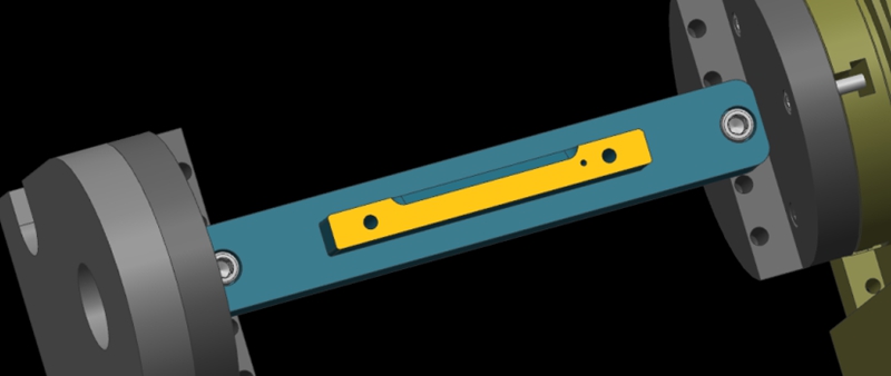
Here, we show a 4-axis rotary table that rotates around the X-axis of a machine tool, where the axis of rotation is called the A-axis. In a word, all we need to do is to determine the Y/Z coordinates of the center of rotation on the 4-axis machine.
In addition, the X coordinate values are determined by the placement of the product, so we won’t go into detail here. The following are the specific steps to determine the center of rotation.
Step 1: Calibrate the Fixture Reference Plane
Firstly, use the calibration table to calibrate the fixture datum plane (the yellow surface). Then, set the calibrated datum plane to the 0 degree position of the A-axis.
Step 2: Set the Fixture Datum Plane
After setting the datum plane, we need to rotate the A-axis 90 degrees positive. Then, use a centering bar to measure the machine position where the datum plane is located. In the relative coordinate setting, set the Y coordinate to “0”.
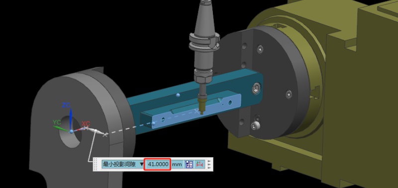
Step 3: Measure the Value of the Datum Plane
Next, rotate the A-axis 180 degrees in the negative direction. Same as the last step, we need to measure the machine position on the other side of the datum using the centering bar. Then, check the current relative Y value of the machine. For example, if we assume the Y value is “92mm”, the centering diameter is 10mm centering diameter, and the fixture datum to the rotary table is 41mm.
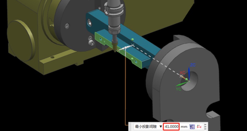
Step 4: Determine the Position of the Rotation Center in the Y-axis
Referring to the values in the previous step, we can calculate that 92/2 = 46mm, so half of the Y value of 46mm. Then, we move the centering bar 46mm negatively towards the Y-axis.
As shown by the picture, the centering bar is now just aligned with the rotational axis of the rotary table. At the time, the position of the alignment point is the zero point of the Y value of the machine. In this way, we have completed half of the operation work.

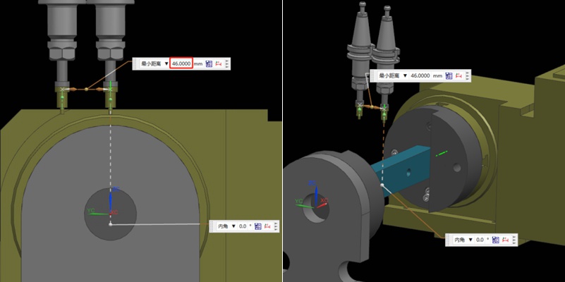
Step 5: Find the Position of the Rotation Center in the Z-axis
Finding the Z value is relatively simple. After the rotary table returns to the A0 position, the zero point of the Z-axis of the rotary axis can be determined by moving down 41mm with the datum surface as the calculation base. This value is calculated using the formula “(92-10)/2”, where 92 is the Y-value found earlier and 10 is the diameter of the centering bar. By applying this formula, the Z value is determined.
Finally, the intersection of the Z and Y axis is the rotation center around the X axis. With these steps, we can determine the rotation center of the 4-axis rotary table.
Recomendações
How To Create A Prototype With Steps: An Expert Guide
A prototype is an early version or physical model of a product idea that manufacturers can test and refine before investing in mass production. It acts as a product template and provides a practical approach to understanding a product’s appearance and function before production. When developing a product, product teams create a product prototype to test the product’s usability, design, and performance, gather user feedback, identify potential issues in the early stages, and identify possib...

Press Fit Tolerance: Defination, Practices, and Calculation
The manufacturing industry is highly precision-centric, where even the slightest of margins can create huge differences in product quality, cost, and utility. This article discusses the topic of press fitting, where a few micrometers of deviation dictates the criterion for part failure. So, what is press fit and, the factors influencing press fit tolerancing, and present an example of a press fit calculator. We will also share some key tips to keep in mind while designing components for p...

Explicação do subsídio de maquinagem: O seu cálculo e as suas implicações
A tolerância de maquinagem é um conceito fundamental no fabrico. É uma prática de engenharia comum na maquinagem de precisão CNC, garantindo a precisão dimensional, a qualidade da superfície e a produção de componentes fiáveis e funcionais para uma série de indústrias, incluindo a aeroespacial, a de defesa e a médica. Este artigo tenta responder à pergunta: o que é a permissão de maquinagem? Iremos aprofundar o conceito de margem de maquinagem e discutir a razão pela qual os maquinistas deixam a margem de maquinagem...

What Is SFM? A Complete Guide To Surface Feet Per Minute In Machining
SFM, meaning Surface Feet per Minute in CNC machining, measures how fast a cutting tool moves across a workpiece. It is expressed in feet per minute. SFM combines the tool or workpiece diameter with the spindle speed (RPM). A larger diameter or higher RPM results in a higher SFM. Machinists use surface feet per minute to determine the best cutting speed for a material. Different materials have recommended SFM values for optimal performance. For example, 303 annealed stainless steel has an...

