加工金屬時產生刀痕的原因與解決方案
Precision metal parts are often manufactured using various precision machining technologies, with CNC machining being a common method. Usually, precision parts typically demand high standards for both dimensions and appearance.
Therefore, when using CNC machining metals such as aluminum and copper, the occurrence of tool marks and lines on the finished product’s surface is a concern. This article discusses the reasons that cause tool marks and lines during the machining of metal products. We also propose potential solutions.
Insufficient Clamping Force of Fixtures
Causes: Some cavity metal products need to use vacuum fixtures, and may struggle to generate sufficient suction due to the presence of surface irregularities, resulting in tool marks or lines.
Solution: To mitigate this, consider transitioning from simple vacuum suction to vacuum suction combined with pressure or lateral support. Alternatively, explore alternative fixture options based on specific part structures, tailoring the solution to the particular problem.
Process-related Factors
Causes: Certain product manufacturing processes may contribute to the issue. For instance, products like tablet PC rear shells undergo a sequence of machining steps involving punching side holes followed by CNC milling of the edges. This sequence can lead to noticeable tool marks when milling reaches the side-hole positions.
Solution: A common instance of this problem occurs when the aluminum alloy is chosen for electronic product shells. To resolve it, the process can be modified by replacing the side hole punching plus milling with only CNC milling. At the same time, ensuring consistent tool engagement and reducing uneven cutting when milling.
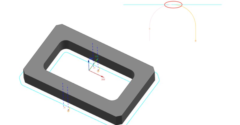
Inadequate Programming of Tool Path Engagement
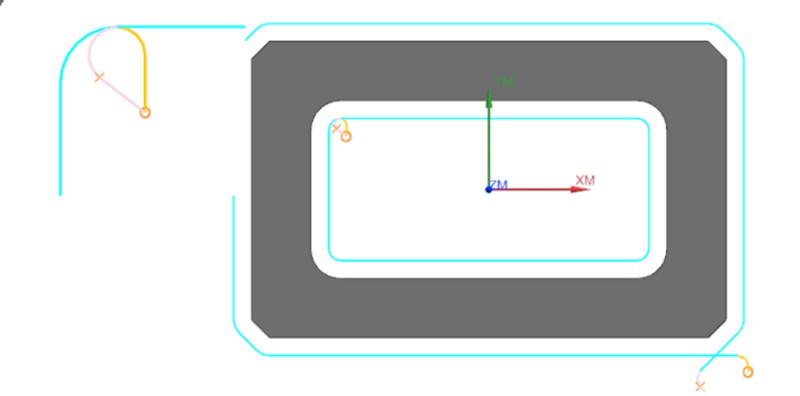
Causes: This issue commonly arises during the 2D contour machining phase of product production. Poorly designed tool path engagement in the CNC program, leaving traces at the entry and exit points of the tool.
Solution: To address the challenge of avoiding tool marks at entry and exit points, a typical approach involves introducing a slight overlap in tool engagement distance (approximately 0.2mm). This technique serves to circumvent potential inaccuracies in the machine’s lead screw precision.
While this strategy effectively prevents the formation of tool marks, it causes an element of repetitive machining when the material of the product is a soft metal. Consequently, this section may exhibit variations in texture and color compared to other areas.
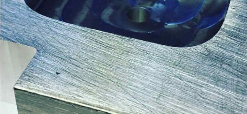
Fish Scale Patterns on Flat Machined Surfaces
Causes: Fish scale or circular patterns appearing on the product’s flat surfaces. The cutting tools used for processing soft metals such as aluminum/copper are generally alloy material mills with 3 to 4 flutes. They have a hardness ranging from HRC55 to HRC65. These milling cutting tools are performed using the bottom edge of the tool, and the part surface may develop distinctive fish scale patterns, impacting its overall appearance.
Solution: Commonly observed in products with high flatness requirements and flat surfaces featuring recessed structures. A remedy is to switch to cutting tools made from synthetic diamond material, which helps achieve smoother surface finishes.
Aging and Wear of Equipment Components
Causes: The tools mark on the product surface is attributed to the aging and wear of the equipment’s spindle, bearings, and lead screw. Additionally, inadequate CNC system backlash parameters contribute to pronounced tool marks, particularly when machining rounded corners.
Solution: These issues stem from equipment-related factors and can be addressed by targeted maintenance and replacement.
Conclusion
Achieving an ideal surface in the CNC machining metals demands useful approaches. There are different methods to avoid tool marks and lines that involve a combination of equipment maintenance, fixture enhancements, process adjustments, and programming refinements. By understanding and rectifying these factors, manufacturers can ensure that precision components not only meet dimensional criteria but also exhibit the desired aesthetic qualities.
建議
CNC 加工成本:什麼會影響及如何節省成本?
CNC 加工是一種用於製造精密零件和複製驚人設計的技術。CNC 加工有許多優點,例如可提高零件生產速度。由於是由電腦控制,因此也可減少製造過程中的人為錯誤。然而,許多人似乎並不了解其成本背後的原理。您使用的機器和材料會影響價格。時至今日,許多客戶仍在煩惱如何計算 CNC 加工成本。隨著數控加工技術的不斷進步...

如何防止大型薄壁殼體零件在 CNC 加工過程中發生翹曲和變形?
大型薄壁殼體零件在加工過程中容易產生翹曲與變形。在本文中,我們將介紹一個大型薄壁零件的散熱片案例,討論在一般加工製程中的問題。此外,我們也會提供一個最佳化的製程與夾治具解決方案。讓我們進入正題!本案例是關於一個由 AL6061-T6 材料製成的殼狀零件。以下是它的確切尺寸。整體尺寸:455*261.5*12.5mm支撐壁厚:2.5mm散熱片厚度:1.5mm...

階級車削 vs. 錐度車削:有何差異?
Turning is a fundamental machining operation that has supported the manufacturing industry for centuries. It continues to evolve and is a core manufacturing technique to this day. This article will discuss two types of turning operations: step turning vs taper turning. We will explore the step process and taper turning process and explain their differences.Turning is essentially a cutting operation where a sharp cutting tool shapes a rotating workpiece by removing material from its surfa...

銑削種類說明:瞭解所有銑削作業
毫無疑問,銑削加工是製造業的骨幹,在航空航天、汽車、醫療和國防等行業的高品質生產中發揮著直接作用。銑削作業具有高度的通用性,能夠精準快速地處理複雜的幾何形狀。在這篇文章中,我們將討論 CNC 銑削的基本原理,並解釋各種銑削操作,以協助您選擇適合應用的銑削類型。

