操作 4 軸 CNC 機床時,如何確定旋轉軸的旋轉中心?
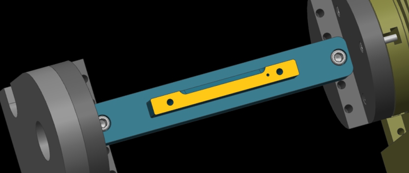
Here, we show a 4-axis rotary table that rotates around the X-axis of a machine tool, where the axis of rotation is called the A-axis. In a word, all we need to do is to determine the Y/Z coordinates of the center of rotation on the 4-axis machine.
In addition, the X coordinate values are determined by the placement of the product, so we won’t go into detail here. The following are the specific steps to determine the center of rotation.
Step 1: Calibrate the Fixture Reference Plane
Firstly, use the calibration table to calibrate the fixture datum plane (the yellow surface). Then, set the calibrated datum plane to the 0 degree position of the A-axis.
Step 2: Set the Fixture Datum Plane
After setting the datum plane, we need to rotate the A-axis 90 degrees positive. Then, use a centering bar to measure the machine position where the datum plane is located. In the relative coordinate setting, set the Y coordinate to “0”.
Step 3: Measure the Value of the Datum Plane
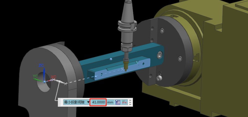
Next, rotate the A-axis 180 degrees in the negative direction. Same as the last step, we need to measure the machine position on the other side of the datum using the centering bar. Then, check the current relative Y value of the machine. For example, if we assume the Y value is “92mm”, the centering diameter is 10mm centering diameter, and the fixture datum to the rotary table is 41mm.
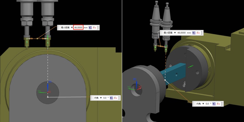
Step 4: Determine the Position of the Rotation Center in the Y-axis
Referring to the values in the previous step, we can calculate that 92/2 = 46mm, so half of the Y value of 46mm. Then, we move the centering bar 46mm negatively towards the Y-axis.
As shown by the picture, the centering bar is now just aligned with the rotational axis of the rotary table. At the time, the position of the alignment point is the zero point of the Y value of the machine. In this way, we have completed half of the operation work.

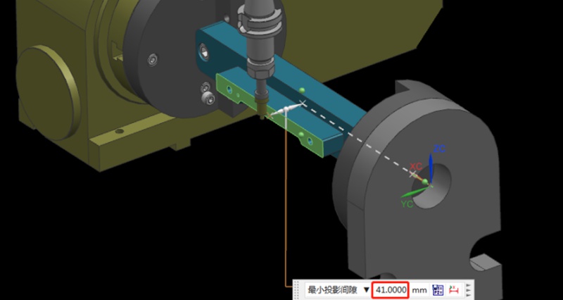
Step 5: Find the Position of the Rotation Center in the Z-axis
Finding the Z value is relatively simple. After the rotary table returns to the A0 position, the zero point of the Z-axis of the rotary axis can be determined by moving down 41mm with the datum surface as the calculation base. This value is calculated using the formula “(92-10)/2”, where 92 is the Y-value found earlier and 10 is the diameter of the centering bar. By applying this formula, the Z value is determined.
Finally, the intersection of the Z and Y axis is the rotation center around the X axis. With these steps, we can determine the rotation center of the 4-axis rotary table.
建議
Press Fit Tolerance: Defination, Practices, and Calculation
The manufacturing industry is highly precision-centric, where even the slightest of margins can create huge differences in product quality, cost, and utility. This article discusses the topic of press fitting, where a few micrometers of deviation dictates the criterion for part failure. So, what is press fit and, the factors influencing press fit tolerancing, and present an example of a press fit calculator. We will also share some key tips to keep in mind while designing components for p...

CNC 加工成本:什麼會影響及如何節省成本?
CNC 加工是一種用於製造精密零件和複製驚人設計的技術。CNC 加工有許多優點,例如可提高零件生產速度。由於是由電腦控制,因此也可減少製造過程中的人為錯誤。然而,許多人似乎並不了解其成本背後的原理。您使用的機器和材料會影響價格。時至今日,許多客戶仍在煩惱如何計算 CNC 加工成本。隨著數控加工技術的不斷進步...

CNC Acrylic Machining: All You Need To Know Machined Acrylic Parts
Today we are going to look at the manufacturing processes of acrylic polymer or optical prototyping. It is one of the most widespread plastics all over the world and a prominent competitor to glass and polycarbonate. Due to the fact that acrylic parts are used in a lot of industry areas, it seems a good idea to look into its manufacturing processes, specifically CNC acrylic machining since that is the process that is present in almost any kind of acrylic production. In this article, we wi...

加工金屬時產生刀痕的原因與解決方案
精密金屬零件通常使用各種精密加工技術製造,其中 CNC 加工是一種常見的方法。通常,精密零件通常對尺寸和外觀都有很高的要求。因此,在使用 CNC 加工鋁和銅等金屬時,成品表面出現刀痕和線條是一個值得關注的問題。本文將討論在加工金屬製品過程中造成刀痕和線條的原因....。

