Suche im gesamten Bahnhof Aluminium Teile twentytwentyfive

Wie vermeidet man Maschinenkollisionen während des Bearbeitungsprozesses?

Fallstudien Ressourcen 128

Machine collision has always been an inevitable challenge in prototype and part machining. Operator errors, such as failing to perform tool settings, can lead to crashes. It will result in broken tools, scrapped workpieces, and reordering and reprocessing materials.

In addition, without the automatic tool setter, manual tool setting when entering Z-value data error can also cause machine collision. In this article, we will share our summarized experiences to help you avoid this issue.

broken workpiece

Three Main Causes Of Machine Crashes

Before understanding how to avoid workpiece damage caused by machine collision, it is essential to understand the main reasons behind them.

Toolpath Issues By Programming Engineers

The CNC programming software MasterCam uses a method of adopting elements of surfaces and lines for machining. If the auxiliary surfaces are not fully enclosed and have missing areas, there is a risk of machine collision. However, these risks can be identified through computer-simulated machining verification, which can check for overcuts on the workpiece to avoid the risk.

CNC Operator’s Operational Issues

There are commonly three setting problems that will cause the crashing.

  • Calling the Wrong Program for Machining: CNC machine operations are controlled by program instructions. When calling a program for machining, the operator must verify that the program name, tools, and clamping lengths match the program sheet.
  • Calling the Wrong Coordinate: Sometimes, multiple workpieces are machined simultaneously on a CNC machine, there are multiple coordinates such as G54 and G56. Therefore, Calling the wrong coordinate can also lead to machine collision.
  • Missing Tool Setting or Incorrect Z-Value Data Entry: After the program starts, the tool movement needs to match the actual position of the tool tip with the Z-value data displayed on the machine screen. If there is a significant discrepancy between them, the machining process should be immediately stopped to recheck the program and tool setting data for errors.

Mechanical Failures or Tool Holder Wear

While the probability of this happening is low with regular maintenance and care of equipment and tools, it can still lead to tool drops and crashes during machining.

How To Prevent Machine Collision Using Trial Cutting Methods?

After understanding the main causes of machine collision, it should implement effective preventive measures. In this section, we will focus on how to adopt trial-cutting methods to avoid machine collision when tool setting is missed or Z-value data entry errors occur.

Trial Cutting Method for Workpieces with Frames

When a workpiece has a frame, the boundary line is typically used for trial cutting. As shown in the figure, the yellow line represents the boundary line, and only a short distance needs to be trial cut.

trial cutting method

In the trial cutting process, the Z-value height should be the same as the border height. With a 200mm straight distance and a feed rate of 3000F/MIN, the trial machining time is 4 seconds, plus about 2 seconds for lowering and raising the tool, totaling around 6 seconds.

The above is a simple method that uses the same spot for trial cutting with each tool. So it is only to verify if the tool setting is too deep, avoiding overcutting or crashing.

Trial Cutting in Different Machining Areas

In most cases, except for face sweeping tools, each machining tool should perform trial machining in different areas. In the trial cutting process, the machining depth can be set to the frame plane -0.02MM. If the tool setting is correct, a slight machining mark will be visible after trial machining; if too deep, a more profound mark will appear; if too high, no mark will be seen.

Since this method relies on visual judgment, the error margin is estimated to be 0.05-0.1MM. Unlike using the same spot for trial cutting with each tool, this method checks if the tool setting is too high.

As the marked number in the above figure, the number of trial cuts can be adjusted based on the number of machining tools. However, each trial cut requires a manual judgment, taking about 2 minutes per trial, making it unsuitable for mass production.

Face Sweeping Machining for Workpieces with Frames

For parts with borders that require face machining, the first face sweeping tool does not need trial machining as its starting point is outside the workpiece.

cutting tool path

Trial Cutting for Workpieces without Frames

For workpieces without frames, such as those needing re-machining after 3-axis processing of both front and back sides. The trial cutting is done on the positioning reference or fixed block to avoid machine collision.

Types Of Milling Explained: Know All Milling Operations

Milling is inarguably the backbone of the manufacturing industry, playing a direct role in high-quality production in industries including aerospace, automotive, medical, and defense. Milling operations are highly versatile and capable of handling complex geometries with precision and speed. In this article, we will discuss the fundamentals of CNC milling and explain various milling operations, helping to choose the right milling type for your applications.Milling is a machining process t...

Types Of Milling Explained: Know All Milling Op...

Presssitz-Toleranz: Definition, Praktiken und Berechnung

Die verarbeitende Industrie ist sehr präzisionsorientiert, und selbst geringste Abweichungen können zu großen Unterschieden in der Produktqualität, den Kosten und dem Nutzen führen. Dieser Artikel befasst sich mit dem Thema Presspassung, bei der wenige Mikrometer Abweichung das Kriterium für das Versagen eines Teils sind. Wir erklären, was Presspassung ist, welche Faktoren die Presspassungstoleranz beeinflussen, und stellen ein Beispiel für einen Presspassungsrechner vor. Außerdem geben wir Ihnen einige wichtige Tipps, die Sie bei der Konstruktion von Bauteilen für die Presspassung...

Presssitz-Toleranz: Definition, Praktiken, und...

Wie bestimmt man das Rotationszentrum eines Rotationskörpers beim Betrieb einer 4-Achsen-CNC-Maschine?

Heutzutage ist ein vierachsiger Rundtisch ein gängiges Gerät in der Maschinenwerkstatt. Um die Bearbeitung mehrerer Flächen in einer Koordinate abschließen zu können, müssen die Programmierkoordinaten mit den Koordinaten des Rundtisches synchronisiert werden. In diesem Artikel wird eine Methode zur Bestimmung des Rotationszentrums eines 4-Achsen-Rundtisches vorgestellt: Ein 4-Achsen-Rundtisch, der sich um die X-Achse einer Werkzeugmaschine dreht, wobei die Drehachse als A-Achse bezeichnet wird. Mit einem Wort,...

Bestimmen des Rotationszentrums eines Rotationskörpers ...

CNC Acrylic Machining: All You Need To Know Machined Acrylic Parts

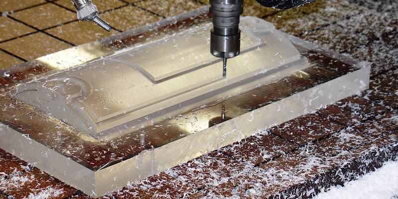
Today we are going to look at the manufacturing processes of acrylic polymer or optical prototyping. It is one of the most widespread plastics all over the world and a prominent competitor to glass and polycarbonate. Due to the fact that acrylic parts are used in a lot of industry areas, it seems a good idea to look into its manufacturing processes, specifically CNC acrylic machining since that is the process that is present in almost any kind of acrylic production. In this article, we wi...
CNC Acrylic Machining: All You Need To Know Mac...
Erweitern Sie mehr!