Suche im gesamten Bahnhof Aluminium Teile twentytwentyfive

Wie bearbeitet man polyedrische Aluminiumteile durch die Entwicklung von Prozessrouten und Vorrichtungen?

Fallstudien Ressourcen 97

In the field of machining and manufacturing, selecting the appropriate machining strategy is important for improving production efficiency. In common, the polyhedral machined parts have complex geometries and tight tolerance requirements. So how choosing a suitable processing route for machining such parts requires comprehensive considerations.

In this article, Washxing provides an analysis of different process routes for polyhedral aluminum parts and compares the 3+2-axis CNC machining and 3-axis CNC machining methods. We also highlight its fixture design considerations. Let’s get into it.

aluminum polyhedral part drawing

Product Introduction

The product is a precision aluminum polyhedral component used in semiconductor equipment, with a production quantity of 800 pieces. Due to the need for assembly with other parts, it requires high dimensional tolerances, especially for hole tolerances and geometric tolerances. Additionally, these machined parts require black anodizing to prevent oxidation and improve wear resistance.

Key Dimensions Machining Requirements

  • Flatness: 0.01;
  • Two ∅2.3+0.015mm precision holes, with a positional tolerance of 0.05mm;
  • Two ∅3.5+0.015mm precision holes, with a positional tolerance of 0.05mm;
  • Two ∅2.5+0.015mm precision holes, with a positional tolerance of 0.05mm;
  • Perpendicularity relative to Datum A: 0.02mm
  • Linear dimension: 38.88-0.02mm

key machining requirements of polyhedral part

Machinability Analysis

Let‘s check the machinability characteristics of this polyhedral component. The maximum external dimensions of the product are 46.88×16.41×10.91 mm. Its machining tolerance requirements are as follows:

  • The strictest dimension tolerance of the part is 38.88-0.02 mm, which can be maintained by two times fine milling at the same path.
  • Other tolerances of ±0.03 mm and above can be guaranteed with a single fine milling.
  • The three sets of +0.015 mm precision holes can be ensured through precision reaming.
  • Positional accuracy is best achieved by machining the measured hole and reference datum in the same process.
  • Perpendicularity of 0.02mm can be maintained by machining in the same process as Datum A or using Datum A as the reference.
  • The flatness of 0.01 requires proper machining parameters. So this finishing machining should employed later in the whole process to minimize deformation.

Finally, the product also requires age hardening to release material stress and ensure long-term dimensional stability. Since the product is not big and the material removal rate is less than 80%, a single precipitation heat treatment before machining is sufficient.

Process Route Comparison for Machining Aluminum Polyhedral Parts

Comparing the two process routes in the following picture shows that the 3-axis machining solutions require five process procedures, each needing a custom fixture. In contrast, using 3+2 axis machining, supplemented by a 3-axis machine to remove residual material at the joint position, requires only two process procedures and fewer fixtures.

For small batch orders from 50 to 1000, the second machining solution has a significant cycle time advantage. At the same time, it better guarantees the key dimensions by completing them in the same process procedure.

two machining routes comparison of polyhedral parts

Combine 3+2-axis with One-Time 3-axis Machining

However, the advantage of the 3-axis machining solution lies in its ability to duplicate many parts per process. So it can improve machine utilization in the machining. On the other hand, the 3+2 axis machine typically processes one part at a time, reducing machine utilization due to the frequent loading and unloading of workpieces. In addition, we need to use machine tool detection probes to compensate for positioning errors during machining changeovers.

During the machining process, we need to take everything into account. Finally, we chose to combine 3+2 axis machining and a one-time 3-axis process for producing the polyhedral parts, which is the most efficient processing solution.

Highlights of Fixture Design

As we mentioned above, the 5-axis machining route typically processes one part at a time. However, through careful analysis and design, we can achieve machining 2 workpieces in one setup. Combined with zero-point quick-change bases, as shown in Figure 3, two parts can be machined simultaneously. We named these A/B bases, where the A base processes inside the machine while the B base is clamped outside. This improves the problem of under-utilization of machining time on 5-axis machines.

fixture design of polyhedral part

Schlussfolgerung

This article compared two process routes for machining an aluminum polyhedral part. We should consider the product order quantity and dimensional requirements during the CNC machining process. Finally, the combined 3+2-axis and 3-axis process solution was selected, and Washxing successfully delivered the order with quality and effectiveness. If you have any machining requirements for your project, just contact Washxing for professional custom CNC machining services.

Wie lassen sich Verzug und Deformation bei großen und dünnwandigen Schalenteilen während der CNC-Bearbeitung verhindern?

Große, dünnwandige Schalenteile können sich während der Bearbeitung leicht verziehen und verformen. In diesem Artikel stellen wir einen Kühlkörper mit großen und dünnwandigen Teilen vor, um die Probleme bei der regulären Bearbeitung zu diskutieren. Außerdem stellen wir eine optimierte Prozess- und Vorrichtungslösung vor. Legen wir los! In diesem Fall geht es um ein Schalenteil aus dem Werkstoff AL6061-T6. Hier sind seine genauen Abmessungen. Gesamtabmessung: 455*261.5*12.5mmStützwanddicke: 2.5mmWärmesenke-Dicke: 1.5mmH...

Wie man Verwerfungen und Verformungen in großen...

CNC-Bearbeitung - Entwurf für die Fertigung: Technischer Leitfaden für Experten

Efficient CNC design is key to balancing functionality, cost, and production efficiency. By following these guidelines, you can avoid common design challenges, improve manufacturability, and streamline the production process. From minimizing thin walls and deep cavities to setting reasonable tolerances, each recommendation in this solution helps simplify machining while ensuring quality. Let’s get to it!The depth of cavities and grooves is typically limited by the cutting tool diameter us...
CNC-Bearbeitungsdesign für die Fertigung: Experte ...

CNC Acrylic Machining: All You Need To Know Machined Acrylic Parts

Today we are going to look at the manufacturing processes of acrylic polymer or optical prototyping. It is one of the most widespread plastics all over the world and a prominent competitor to glass and polycarbonate. Due to the fact that acrylic parts are used in a lot of industry areas, it seems a good idea to look into its manufacturing processes, specifically CNC acrylic machining since that is the process that is present in almost any kind of acrylic production. In this article, we wi...
CNC Acrylic Machining: All You Need To Know Mac...

Wie vermeidet man Maschinenkollisionen während des Bearbeitungsprozesses?

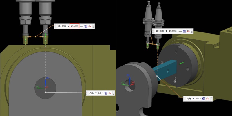
Machine collision has always been an inevitable challenge in prototype and part machining. Operator errors, such as failing to perform tool settings, can lead to crashes. It will result in broken tools, scrapped workpieces, and reordering and reprocessing materials. In addition, without the automatic tool setter, manual tool setting when entering Z-value data error can also cause machine collision. In this article, we will share our summarized experiences to help you avoid this issue. Bef...

Wie man Maschinenkollisionen bei der Bearbeitung vermeidet...
Erweitern Sie mehr!