금속 가공 시 공구 마크의 원인과 해결 방법
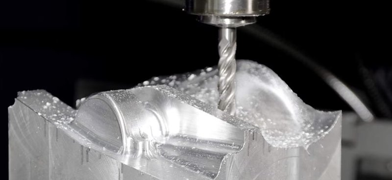
Precision metal parts are often manufactured using various precision machining technologies, with CNC machining being a common method. Usually, precision parts typically demand high standards for both dimensions and appearance.
Therefore, when using CNC machining metals such as aluminum and copper, the occurrence of tool marks and lines on the finished product’s surface is a concern. This article discusses the reasons that cause tool marks and lines during the machining of metal products. We also propose potential solutions.
Insufficient Clamping Force of Fixtures
Causes: Some cavity metal products need to use vacuum fixtures, and may struggle to generate sufficient suction due to the presence of surface irregularities, resulting in tool marks or lines.
Solution: To mitigate this, consider transitioning from simple vacuum suction to vacuum suction combined with pressure or lateral support. Alternatively, explore alternative fixture options based on specific part structures, tailoring the solution to the particular problem.
Process-related Factors
Causes: Certain product manufacturing processes may contribute to the issue. For instance, products like tablet PC rear shells undergo a sequence of machining steps involving punching side holes followed by CNC milling of the edges. This sequence can lead to noticeable tool marks when milling reaches the side-hole positions.
Solution: A common instance of this problem occurs when the aluminum alloy is chosen for electronic product shells. To resolve it, the process can be modified by replacing the side hole punching plus milling with only CNC milling. At the same time, ensuring consistent tool engagement and reducing uneven cutting when milling.
Inadequate Programming of Tool Path Engagement
Causes: This issue commonly arises during the 2D contour machining phase of product production. Poorly designed tool path engagement in the CNC program, leaving traces at the entry and exit points of the tool.
Solution: To address the challenge of avoiding tool marks at entry and exit points, a typical approach involves introducing a slight overlap in tool engagement distance (approximately 0.2mm). This technique serves to circumvent potential inaccuracies in the machine’s lead screw precision.
While this strategy effectively prevents the formation of tool marks, it causes an element of repetitive machining when the material of the product is a soft metal. Consequently, this section may exhibit variations in texture and color compared to other areas.
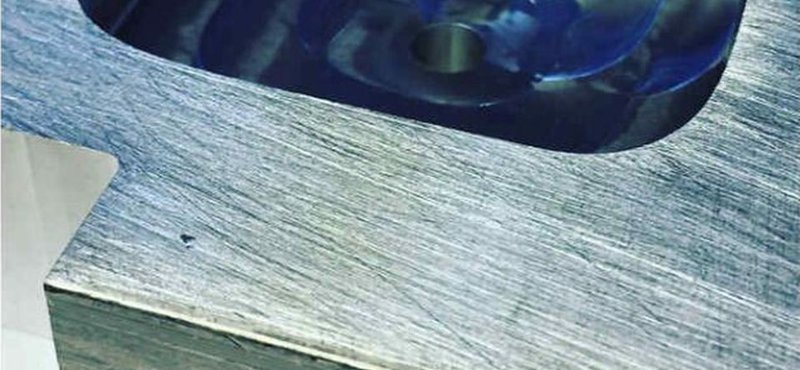
Fish Scale Patterns on Flat Machined Surfaces
Causes: Fish scale or circular patterns appearing on the product’s flat surfaces. The cutting tools used for processing soft metals such as aluminum/copper are generally alloy material mills with 3 to 4 flutes. They have a hardness ranging from HRC55 to HRC65. These milling cutting tools are performed using the bottom edge of the tool, and the part surface may develop distinctive fish scale patterns, impacting its overall appearance.
Solution: Commonly observed in products with high flatness requirements and flat surfaces featuring recessed structures. A remedy is to switch to cutting tools made from synthetic diamond material, which helps achieve smoother surface finishes.
Aging and Wear of Equipment Components
Causes: The tools mark on the product surface is attributed to the aging and wear of the equipment’s spindle, bearings, and lead screw. Additionally, inadequate CNC system backlash parameters contribute to pronounced tool marks, particularly when machining rounded corners.
Solution: These issues stem from equipment-related factors and can be addressed by targeted maintenance and replacement.
결론
Achieving an ideal surface in the CNC machining metals demands useful approaches. There are different methods to avoid tool marks and lines that involve a combination of equipment maintenance, fixture enhancements, process adjustments, and programming refinements. By understanding and rectifying these factors, manufacturers can ensure that precision components not only meet dimensional criteria but also exhibit the desired aesthetic qualities.
권장 사항
브리지 생산 및 제조: 주요 단계 및 이점
최종 생산 공정을 채택하려면 특히 프로토타입 제작이나 소량 생산 과정에서 수많은 시행착오와 실패가 수반되는 경우가 많습니다. 기업은 접근 방식에 확신을 가질 때까지 일시적으로 생산 방법을 선택할 수 있습니다. 브리지 생산은 이러한 임시적인 전략을 말하며, 보다 안정적인 제조 프로세스를 개발하는 동안 지속적인 운영을 가능하게 합니다. 브리지 생산을 이해하는 것은 제품 개발을 개선하고 운영을 가속화하기 위해 매우 중요합니다. 이 문서...

제조용 CNC 가공 설계: 전문가 기술 가이드
효율적인 CNC 설계는 기능, 비용, 생산 효율성의 균형을 맞추는 데 핵심입니다. 이 가이드라인을 따르면 일반적인 설계 문제를 방지하고 제조 가능성을 개선하며 생산 프로세스를 간소화할 수 있습니다. 얇은 벽과 깊은 캐비티 최소화부터 합리적인 공차 설정까지, 이 솔루션의 각 권장 사항은 가공을 간소화하는 동시에 품질을 보장하는 데 도움이 됩니다. 시작하겠습니다! 캐비티와 홈의 깊이는 일반적으로 절삭 공구 직경에 의해 제한됩니다...

엔지니어링 도면과 그 요소에 대해 알아야 할 모든 것
그림을 그리거나 그림을 그리는 것은 자신의 생각을 전달하는 훌륭한 기술입니다. 산업 디자인이라는 넓은 개념에서 엔지니어링 드로잉 또는 테크니컬 드로잉은 실제 물체를 제작하는 디자이너에게 필수적인 기술입니다. 따라서 엔지니어링 드로잉은 몇 가지 중요한 목적을 수행하는 엔지니어링 설계의 기본 중 하나입니다. 엔지니어링 도면은 필수 설계 정보를 담고 있는 표준 기술 도면으로, 서로 다른 엔지니어 간의 커뮤니케이션 모드입니다.

How To Create A Prototype With Steps: An Expert Guide
A prototype is an early version or physical model of a product idea that manufacturers can test and refine before investing in mass production. It acts as a product template and provides a practical approach to understanding a product’s appearance and function before production. When developing a product, product teams create a product prototype to test the product’s usability, design, and performance, gather user feedback, identify potential issues in the early stages, and identify possib...

